Fabbster 3D printer
The Fabbster is a low cost 3D printer kit that can be assembled by people with some do-it-yourself skills.
More later. I am still assembling !
At some point I will split the page, e.g. move assembly to a separate page after I am done with it
- Daniel K. Schneider 14:11, 24 April 2012
The fabbster kit
Important. This article refers to a "pilot program" printer and the draft manual version 1.10 and not the "final" home-user version.
Getting it The kit is sold through retailers and costs about 1500 € (incl. VAT., e.g. here). It will be shipped sometimes soon (May 2012?). I got ours for 500 € through their (March 2012) pilot program.
Software
- A basic slicer program (STL to machine code configurator/translator) from Netfabb is included in the price.
- The printer comes with an electronic box that can print either through a connected PC or via an USB stick.
- Driver software for Windows XP/VISTA/7 can be downloaded from the wiki.
Materials
- Custom made ABS sticks or 3mm ABS rolls
- PLA sticks or rolls
The parts
Unlike the RapMan, the fabbster is based on very few different kinds of parts:
- Most of the structure uses so-called "cassettes", i.e. good for most everything 8.5x7.6cm plastic parts
- Most screws and bolts have the same size.
The assembly manual
- Assembly is described in a bilingual German/English assembly handbook (Version 1.10 is a color PDF file in A4 portrait format and includes 57 pages and about 42 for the assembly process itself.
- Steps are explained on sheets that included the following information:
- Parts (prepare them first)
- A graphic explaining the assembly step
- Some detail views
- A global progress view
Other documentation
- Wiki
- support forums
Assembly time depends:
- On your DYI skills
- On your technical reading skills
- On your capacity to follow instructions (undoing is easy, but adds time)
- On how well you want it to be done
- On how fast (without breaks etc) you plan to work
In my opinion, it can be anything between 3 and 12 hours.
Assembly of the geometry

Important disclaimer.
Notes and tips below refer to a "pilot program" printer and the draft manual version 1.10. Their purpose is to help other pilot program participants. The model that will be shipped to future normal customers will be different: Some parts may be easier to assemble, colors may change, manual will change, etc. - Daniel K. Schneider 17:12, 25 April 2012 (CEST).
Below, we shall not describe the whole assembly since there is a good manual. We just will write down some tips and maybe some problems we will find.
Overall, assembly of the geometry is fairly easy as compared to a RapMan for example.
Preparation
- Retrieve it
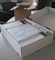
- Before you open the boxes, take a picture. This makes an nice souvenir. More importantly such a picture is useful in case something is damaged as I learned just a week ago. I also ordered a (custom made pre-assembled) Felixprinter and on arrival it was broken. Must have fallen off a truck or something :(
- Inventory
- Open the box. Ideally you should have a fairly big table at your disposal during assembly.
- Make an inventory of the parts. I skipped that, since I trust German efficiency :). The manual includes a part list.
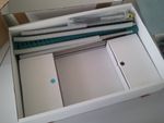
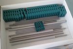
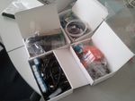
- Inside the box


- Tools needed
- Most tools needed come with the kit: a hammer, 2 hex keys (allen key sin English English) and cutting pliers (clippers)
Additional tools suggested:
- A ruler,
- a (cheap) electronic caliper,
- plastic tape,
- a 2nd hex key (same size as the bigger green one, preferably a high-quality one with a ball end)
- You can use an electric screwdriver, but use minimal force
- strong (cheap) pliers
- a flat metal file and maybe a round one (needle file) too
- Mental preparation
- Look at the pictures at the end of the manual in order to understand what you are going to build !
- Suggestion for the end-user manual
- Insert upfront a graphic that labels the most important elements (axis, names of the motors). e.g. see this
- Table

- Bigger is better

Step 1 - p. 10
Objective: Assembly of the motors
Manual improvement:
- The icon of the B4 screw should be changed, it's really small and black. Although it's ok in the detailed picture.
Tips:
- To keep the two big nuts in place, use some light tape. This allows to put the motor on the table and the plastic on top and you then can add the 4 screws and push in the orange part. You can pull out the tape before you enter the screw (do the other 3 first).
- The orange pulley is hard to push onto the motor shaft. Don't push it too far since it is difficult to pull it out again.
Steps 2 & 3 - p. 11/12
Objective: Assembly of left and right side of the bottom structure
Tips:
- Insert the E4 clamps first
- Tape down the 9 nuts and put the cassette on the table (nuts down)
- Insert the bolts in the other cassette, turn it and press it onto the table so that the bolts will move in.
- Alternatively (faster): Put 4 corner bolts on the table, cassette on top, then insert 4 bolts, then the rest one by one
- The head of a B1 bolt is about 5mm (helps positioning the rod)
Step 4
Objective: Connecting left and right side with front and back rods
- Manual
- Not clear how far to push in the rods (5mm like above) ?
- Tips
- none, this is an easy step. Well, don't forget to push in both rods first.

Step 5
Objective: Create a part of the y axis (opposite the motor in step 7)
Tips:
- Be careful not to forget the anything !
- Holes for the clamps are bit too narrow. Try to push the clamps in with a rod
- Put 4 cassettes under the lower cassette in order to be able to work on it (picture)
- Make sure that the assemble cassettes remain in the middle of the rod (edge to edge distances about 16cm)
Step 6
Objective: Rods of the y-axis
Tips:
- Turn the cassette up, pull out the belt, before inserting the rods
- The linear bearings C2 are in the little blue boxes.
Step 7
Objective: Motor end of the y-axis and fixing the y-rods
Tips:
- Verify that the motor is well attached, i.e. tighten the screws if needed
- Verify that the orange pulley is pushed into the motor shaft like it should, i.e. about 2mm left. Use your new fancy blue pliers to cut a small piece of a 2mm thick object and put it in the hole. A standard small match that you can get for free is about 2mm in diameter
- Make sure that the clamps are well in place
- Finally: remember that it's useless to tighten the screws a lot since you will have to calibrate the whole geometry later, i.e. you will have to pull cassettes out so that the belts are tight and the whole is a prefect rectangle.
Step 8
Objective: Cassette for the plaform that will move forward/backward
Tips:
- Again: You could put three other cassettes underneath the bottom cassette in order to work on it comfortably
- Make sure the that linear bearings fit snugly into place. They should not move.
- Make sure that the belt touches the bottom of the cassette. Only then add the little green piece that will block the belt.
- Then screw 4 corners first and the remove support cassettes and do the rest.

Steps 9 & 12
Objective: Bottom ends of the two z-axis
Tips
- Tighten the screws of the motor
- If you prefer working "flat", look at the picture to the right
- Leave the nuts quite loose, because you will have to insert rods in step 10
Steps 10 & 13
Objective: Z-Rods
(easy)
- Tighten the bolts a bit

Steps 11 & 14
Objective: Top ends of the two z-axis structures
Tips:
- Make sure that the bearings are well pushed down into the casing of the cassette
- Make sure that the belt turns


Step 15
Objective: Stabilizing the top and bottom (connecting the 2 z-axis) (easy)
Tips:
- Insert the rods first
- Lower rod is towards front, upper towards back
- Calibrate a bit: Upper rod should stick in like the lower (i.e. each rod should be pushed in about 5mm. Use the cap of a black (normal) bolt as cue. It's 5mm.

Step 16
Objective: X-axis motor on the z-axis (moving up and down)
Tips:
- Push in 6 black bolts first (middle and outside)
- Make sure that the linear bearings fit snugly, and then push the cassette down
- Do not forget that the belt (one end) must be inside (that was my only big mistake so far and I discovered it on Step 18 ...)
- Do not tighten since you will have to push in rods in step 17
- Finally I find it easier to do step 18 first
Step 17
Objective: Rods and bearings of the X-axis
(easy, but don't forget the linear bearings !)
Step 18
Objective: X-axis - the other end
This is the most difficult assembly step so far. You may ask a person to help.
Tips:
- Push in 6 black bolts first (middle and outside)
- Make sure that the linear bearings fit snugly, and then push the cassette down
- Keep one side of the belt inside

Step 19
Objective: Cassette for extruder
Tips:
- As always, make sure that every thing fits. In particular, be careful to stick the belt "behind" the green piece that will block it.
- In case the belt is too tight (was my case), adjust the geometry, uptight the 4x2 bolts that hold the 3 lower and the upper horizontal rod and gently hammer the cassettes in.

Step 20
Objective: Extruder motor
Tips:
- Attach the green casing to the motor first. Tighten the screws.
- Push down the little orange center gear. I used the hole of cassette for starters, then a border to push it down. I then put the green cover on top an hammered. Make sure its down. Else the the planetary gears won't turn as nicely.
- Grease the planet gears (inside) and assemble. I put the gears into the casing and then added the top, but there may be a better way ....
- Test if you can turn it. There is some resistance though, hopefully not too much ....
Step 21
Objective: Attach the motor to the x-axis cassette
Steps 22 and 23
Objective: Calibration
Tips:
- Open the green plastic box (electronics) and remove the SD card that is taped there.
- Insert the 2 bolts like in the picture (right)
- Then make the case with the electronics fit (distance between the cassettes is about 12cm (a tiny bit less)
- You now likely will have to push the whole vertical frame backwards or forwards a bit
- You probably will have to loosen at least 2x6 of the bolts
- On the other side, I did not attache the other e-box part, but I used a caliper (faster and probably more precise)
Step 24
Objective: Calibration continued (y-axis belt)
Tips:
- Loosen the bolts of the three font cassettes (if needed). I.e. I suggest loosing the 3x5 that are close to the rods.
- Then do the 16cm - 16cm calibration of the y axis (both in front and back). The point is that this axis should be at 90 degrees. Also, you should anticipate step 26, i.e. also try to get the x-axis belt tight.
- Then hammer a tiny bit on each outer cassette until the middle y-axis belt (that will move the platform) is tight.
- I also suggest using a caliper to make distances on both sides equal. I got distances of about 125.8 mm, but this can be different on yours. Depends on how far you pushed in your rods. The more rectangular you geometry is, the better print quality will be (that's what I learned from my RapMan
- In order to test tension (2-3 seconds of vibration), move the gliding cassette to one end. Belts should be tight, but not too tight. Very short vibes means too tight.
Step 25
Objective: Calibration of z-axis
Tips:
- Listen to the sound of the vibrating belts, left and right must be same
- Slide the y-axis (extruder) up/down, it should be smooth
- Once your are done, tighten the lateral bolts
Step 26
Objective: Calibration of x-axis
Tips:
- This is probably the most difficult to fix, since you will have to work on 8 cassettes, i.e. 4 rods. Loosen all the upper rods if hammering doesn't work
- I was lucky and didn't have to change anything, since I paid attention to this step already in step 24 :)
Step 27
Objective 1: Final test
- All three cassettes on the axis move nicely
- All belts vibrate 2-3 seconds
- The geometry should be strictly equal distances between cassettes and 90 degree angles
- If something is wrong, repeat any steps 22-26 above
Objective 2: Tighten
- Now tighten all the bolts. However, there is no need to tighten like a nut (pun intended). If you tighten too much, you could squeeze the linear bearings or even break something.
Assembly of the extruder


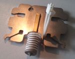
Step 28
Objective: Assemble feeder gear. Do this right ! Besides having a good geometry, having a perfect extruder is mission critical. Bad extruders are the main problem of first generation "reprap" kits. This one looks much tougher :)
Tips: The bearings don't fit well into the metal gears. I used this procedure
- Grease inside the gears
- Use pliers to press the bearings. Press one one end (a bit), then turn, press again, turn etc. That lasts at least 10 minutes for the two. Make sure to use flat pliers (i.e. not cutting pliers) and just press on the rim of the bearings until they are almost fully inserted. Almost means some fraction of a mm.
- I don't think that using a hammer or cooking are good ideas
- I have no clue why the gears should be aligned like in the picture. I mean, they just should fit, but I did it anyhow :)

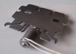
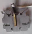
Step 29
Objective: Attach gear to motor
Again, the drive shaft is very hard to drive into the bearing. One solution is to use a metal file to remove some uneven bits (doesn't need much).
Tips:
- Carefully check how you have to assemble. First part is easy.
- Hammer it in (part I): Tap on the shaft and not the bearing on the other side
- Hammer it in (part II): Find two wooden blocks or tables (office furniture will do), put the bearing on top over the gap, then hammer again. For the last bit use a big screwdriver and hammer on top of that. (see picture to the right)
- Make sure that it turns. You can easily loosen the bearing now that the shaft has been hammered it will move easily (just hammer a bit on the other end).
- Next hammer in the orange part. Make sure that is fully down. Again use a big screwdriver or similar for hammering on the metal side of the shaft
- Finally, wiggle it onto the motor
Notes:
- Do not use plumbing pliers since you can damage both the case and the bearing (I almost did)
Step 30
Objective: Heater, i.e. add heating wire to the nozzle (heater)
There was some unevenness at the end of the heater that I evened out with a screwdriver. Also "bend the nose" is a fairly ambiguous term. Finally, the wire I got is either too short or has too much heat isolation at the end.
- Winding the heating wire (resistance)


Tips:
- Make sure that the thermistor heat wire is close to the metal
- Don't pull with force. Inside there is a small wire like in toaster and the will heat !
- Push it in with your thumb starting at the end and do it slowly and carefully or you will regret it later ..
- I then cut off about 1-2 cm from the additional protection, else I couldn't spin the wire up to the top
- Don't understand what "bending the nose" could mean. I just left it as is.

Step 31
Objective: Heat sensor and connectors for heat sensor and resistance wire
Figure on the left side of the manual is wrong. Heat sensor goes into heat sensor hole and not the larger one where the plastic will go ...
Tips:
- Use a paper clip to understand how far the heat sensor should be pushed in. There shouldn't be any problem (dirt inside) but one never knows ...
- Attaching the cables is easy. Just do it right.

Step 32
Objective: Attache the heater to the rest of the extruder
Tips:
- Both cables must be bent outwards. Look at graphic 1 to the right in the manual.
- Resistor wire is too long to fit. Bend it.
- Resistor connector: Turn it sideways (that is: make its depth as small as possible)
- Fit the plate and make sure that no wire is stuck ...
Step 33
(easy)
Tips:
- After adding the fan, tighten all the bolts
- The clip the cover. The bottom doesn't fit 100% because of the bottom bolts but that doesn't matter
To integrate (Fabbster forums)
Assembly: - Look up the latest version of the building instructions here before getting started
- fixating the cable pipes with tape saves 2 to 4 helping hands when it comes to closing the e-box
- try to put as much cable length as possible in the pipes to reduce the cable-in-the-box-mayhem
- the right diagramms of step 30/31 seems to be the "real setup" of the parts ignore the graphics on the left side
- pull the pipe in step 35 to the fitting lenght before putting in the cables
- bend the 80mm pipe in step 37 in the right shape before putting in the cables
- heating the extruder gear in an oven or the kettle to ~50°C+ makes it more easy to assemble the parts it is not wasted to apply some grease in this step
- Temperature sensor: if your sensor does have a red dot you have to change the pin connection instead of cutting off one piece of plastic to connect the pin in reverse direction an other method [in my eyes better way] is to press out the connectors off the temperature connector cable [in between sensor and e-board] with an paper clip and remount them in reverse order [don't forget this fix when installing an other temperature sensor]
Assembly of the cables
Step 34
Objective: Add the e-box
- The bolt behind is not long enough, but don't worry for now...
Step 35/36
Objective: Put the cable of the right z-axis motor into a 36cm conduit
This is so far the most hateful step...
Tips:
- Tape the two connectors together, one after the other, or it won't pass
- Pull the cable through the pipe
- Then turn the machine (back is now in front of you). Else you will get it wrong
- Fold cable 3x to your left (right z-axis motor) and push it in
- Fold cable 4x on your right (left z-axis motor) and push it in
- Now tape the other 2ends
- Pull both ends of the two motor cables through the hole in the cassette (anticipation of step 37)
- Close pipe brackets. This is painfully difficult if you do it wrong. Just clip it on one ring of the tube
- Single cable end. Cable must come out through the hole on the side.
- Double cable end. The motor cable must come out through thole on the side
- Push both cable ends through the hole in the cassette and see if the tube fits into the cassettes on both ends If not, give up (who cares since you always can tape the cables) or restart...
Step 37
Objective: Connect the previous cable
Tips:
- The pipe may be a bit too short. Pull it out (yes it will stretch). But you can do that later ...
Step 38
Objective: Pipe cable of x-axis motor.
Tips:
- Again, cable will enter through the lateral hole of the pipe bracket
- The orange pipe bracket that sits on top of the cassette must stick. Therefore, you will have to open the cassette again (thought that you were done with that ? ... nope)
- Since may hit the structure on top if the platform goes up, you also could have it come out from the end (like the extruder). But since it will not stick I went for the "normal" procedure.
- I opened the cassette and inserted the bracket, even if the manual doesn't explicitly say so. Don't open all the way, just enough to squeeze in the lower part of the bracket. Use a screwdriver to pry it open. Important: Turn the tube outwards toward the back and pull out some cable if you must. These brackets are not symmetrical.
- Test the thing by moving up and down the z-axis !
Step 39
Objective: same as above but for the y axis motor
Tips:
- This time definitely open the cassette and insert the orange pipe bracket. This tube must not move.
to be continued.
Links
- Official
- Fabbster Home
- Fabbster forums
- Fabbster wiki (Includes all the documentation). Sometimes, a wiki page just links to a file, e.g.
- assembly handbook
- drivers and software
Copyright modification
Contents of this page is available as CC-BY, meaning that commercial sites can reuse and remix text or pictures if they cite us.
In addition, Sintermask/Fabbster can copy/paste both texts and pictures associated with this article to their support sites without needing to cite us.
However, given the doubtful quality of the pictures made with a cell phone, I doubt that anyone would like these ;)
- Daniel K. Schneider 22:08, 25 April 2012 (CEST)