Adafruit GEMMA: Difference between revisions
No edit summary |
|||
| (One intermediate revision by the same user not shown) | |||
| Line 2: | Line 2: | ||
|is_part_of_syllabus=E-textile | |is_part_of_syllabus=E-textile | ||
|is_part_of_module=Adafruit Wearables | |is_part_of_module=Adafruit Wearables | ||
|page_previous=MakeCode | |||
|page_next=Adafruit NeoPixel | |page_next=Adafruit NeoPixel | ||
|do_not_show_sub_page=No | |do_not_show_sub_page=No | ||
| Line 8: | Line 9: | ||
|objective=Use the micro-controller to create small prototypes | |objective=Use the micro-controller to create small prototypes | ||
|difficulty=beginner | |difficulty=beginner | ||
|see_also=Adafruit Circuit Playground Express, | |see_also=Adafruit Wearables, | ||
Adafruit Circuit Playground Express, | |||
MakeCode, | |||
Adafruit GEMMA, | Adafruit GEMMA, | ||
Adafruit NeoPixel, | Adafruit NeoPixel, | ||
Adafruit Sensors | Adafruit Sensors | ||
|cat_syllabus=e-textile | |cat_syllabus=e-textile | ||
}} | }} | ||
Latest revision as of 09:28, 8 October 2019
Introduction
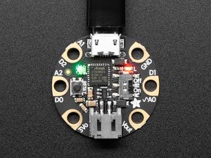
Adafruit GEMMA is a small and cheap e-textile Arduino-compatible board that also can be programmed with CircuitPython. Quote: "The Gemma M0 is a super small microcontroller board, with just enough to build many simple projects. It may look small and cute: round, about the size of a quarter, with friendly alligator-clip sew pads". (Gemma M0 Overview page, August 2019).
As of August 2019, the Gemma M0 version is the most interesting version. It can be programmed with MakeCode / JavaScript, CircuitPython and Arduino. Version V1 and V2 are no longer recommended.
See also:
- Adafruit Circuit Playground Express (the board we recommend to get started)
- MakeCode
- Adafruit Wearables
- Adafruit NeoPixel
- Adafruit Sensors
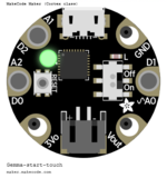
The board
Unlike the Adafruit Circuit Playground Express, this board does not have any sensors. I only has a single RDB LED for output. Therefore, it should be used together with other hardware elements, e.g. Adafruit NeoPixels and any kind of sensor or other input devices described in the Adafruit FLORA page.
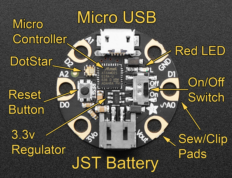
The following information was extracted from the guided tour and the pinouts pages. (retrieved Augus 23, 2019).
Dimensions and price
- Price: $10 / CHF 11
- Diameter: 2.8cm
- Thickness: 5mm (because of the battery connector)
- Weight: ?
Main features
- 48 MHz ATSAMD21 32 bit processor
- 256KB Flash
- 32 KB RAM
- RBG DotStar LED.
- Can be used with Arduino IDE or CircuitPython
- JST battery connector
- ON/OFF Switch
- Reset button
connectivity
- Micro B USB connector. Native USB supported by every OS.
General Purpose Input Ouput (GPIO) Pads
All the 3 GPIO pads can be used as digital inputs, digital outputs, for LEDs, buttons and switches. In additon, all can be used as analog inputs (12-bit ADC) or hardware capacitive touch. Each of the three has unique pad capabilities.
- A0 - connected to PA02 on the ATSAMD21. This pin can be used as a digital I/O with selectable pullup or pulldown, capacitive touch, analog input (use 'A0'), and true analog (10-bit DAC) output. It cannot be used as PWM output.
- A1 - connected to PA05 on the ATSAMD21. This pin can be used as a digital I/O with selectable pullup or pulldown, capacitive touch, analog input (use 'A1'), PWM output, and is also used for I2C clock (SCL), and hardware Serial TX.
- A2 - connected to PA04 on the ATSAMD21. This pin can be used as a digital I/O with selectable pullup or pulldown, capacitive touch, analog input (use 'A2'), PWM output, and is also used for I2C data (SDA), and hardware Serial RX.
Power in/out pads
- 3Vo - This is the 3.3V OUTPUT pad from the voltage regulator, provides up to 500mA at a steady 3.3V. Good for sensors or small LEDs or other 3V devices.
- Vout - Voltage output (connect to either battery or USB power, whichever is highest). Used to power things up to 500mA.
- 1 GND - common ground pin
Drivers
- Windows requires the installation of drivers: Read Windows Driver Installation. Windows 7 will need to install more than windows 10, but that is managed by the sigle *.exe file to download from Adafruit_Windows_Drivers (GitBug)
Programming with MakeCode
So far (Aug 2019), there isn't much documentation.
To program the GEMMA, one has to use the default environment at https://maker.makecode.com/ (unlike the Adafruit Circuit Playground Express, which has its own environment.
First time use
Step 1: (Windows users only)
- Before you start, install the drivers. Download the *.exe file to a local directory and execute it, having admin rights.
Step 2: Ready the board for MakeCode programming (you can do that later also)
- Double press the reset button (in my case) since it was ready for CircuitPython out of the box. The name of the drive was "CircuitPy (D:)". It should be either MAKECODE, METROBOOT or GEMMABOOT. After double pressing the rest button I got GEMMABOOT (D:). which is OK
Creating a new project
Open https://maker.makecode.com/ in a web browser
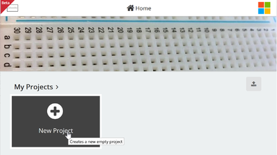
Step 1: Create a new project
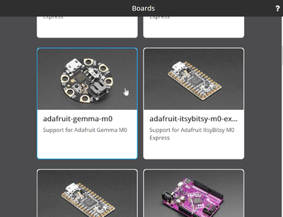
Step 2: Select the gemma board
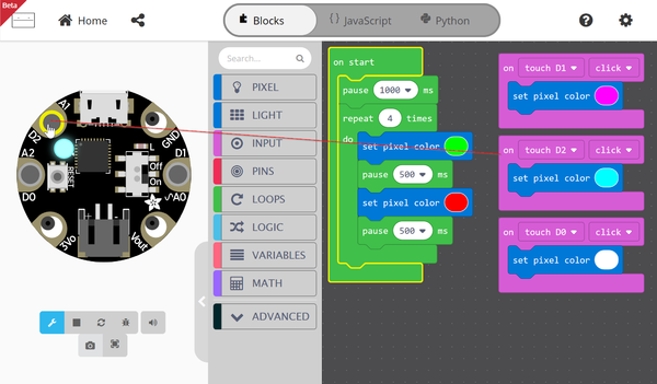
Step 3: Write the program
- See below for an example
Step 4: Save it (actually do that every now and then)
- This will save a PNG file that will have your program code inside (!)
- To edit again, drag and drop the picture into the web editor
- Alternatively you also can export the *.uf2 file. It includes the source code in principle (not tested).
Step 5: Download and flash
- Connect the Board with a USB B cable
- Click on the Download button
- The status LED (top right) will blink while the file transfers.
- After that, the board will reset automatically and your *.uf2 fill will become the current.uf2 file.
Step 6: Tune the program
- After making changes to the program, click on reset button, then do as above in step 5 (i.e. click the download button)
Example
- The following code will have the LED blink green and red four times when started (User presses the reset button once). Notice the pauses.
- The user then can change color
- Pressing A1 (aka D2) : Magenta
- Pressing A0 (aka D1): Pink
- Pressing A2 (aka D0): White
The JavaScript code is below:
input.touchD1.onEvent(ButtonEvent.Click, function () {
    pixel.setColor(0xff00ff)
})
input.touchD2.onEvent(ButtonEvent.Click, function () {
    pixel.setColor(0x00ffff)
})
input.touchD0.onEvent(ButtonEvent.Click, function () {
    pixel.setColor(0xffffff)
})
pause(1000)
for (let i = 0; i < 4; i++) {
    pixel.setColor(0x00ff00)
    pause(500)
    pixel.setColor(0xff0000)
    pause(500)
}
Programming with CircuitPython
“The most exciting part of the Gemma M0 is that while you can use it with the Arduino IDE, we are shipping it with CircuitPython on board. When you plug it in, it will show up as a very small disk drive with main.py on it. Edit main.py with your favorite text editor to build your project using Python, the most popular programming language. No installs, IDE or compiler needed, so you can use it on any computer, even ChromeBooks or computers you can't install software on. When you're done, unplug the Gemma M0 and your code will go with you.”
Links
- Adafruit GEMMA M0 Product Page.
- Overview
Acknowledgement
Pictures as well as some text was reproduced from the Adafruit GEMMA documentation. Some pictures are available under a CC BY-NC-SA license. Others are copyright AdaFruit and "all rights reserved" and reproduced with permission. Before you reuse any picture from this website, make sure to look at the license information.
