OpenScad beginners tutorial
Introduction
“OpenSCAD is a software for creating solid 3D CAD objects. It is free software and available for Linux/UNIX, MS Windows and Apples OS X. Unlike most free software for creating 3D models (such as the famous application Blender) it does not focus on the artistic aspects of 3D modelling but instead on the CAD aspects. Thus it might be the application you are looking for when you are planning to create 3D models of machine parts but pretty sure is not what you are looking for when you are more interested in creating computer-animated movies. OpenSCAD is not an interactive modeller. Instead it is something like a 3D-compiler that reads in a script file that describes the object and renders the 3D model from this script file (see examples below). This gives you (the designer) full control over the modelling process and enables you to easily change any step in the modelling process or make designes that are defined by configurable parameters.” (http://openscad.org/, retrieved 22:58, 17 March 2010 (UTC)
The software - compiling scad code
- To compile (see the result)
- menu: Compile
- or menu: Reload and compile. I prefer using an exteranl editor (i.e. emacs to get "real" indentation support and good syntax high-lighting in java mode).
- To render for real and to export
- menu: Design-> Compile and render
- menu: Design-> Export as .STL
Some 3D principles
It's good to undestand some of the 3D terminology, in order to be able to follow instruction or to figure out why things went wrong...
- “The basic object used in mesh modeling is a vertex, a point in three dimensional space. Two vertices connected by a straight line become an edge. Three vertices, connected to the each other by three edges, define a triangle, which is the simplest polygon (face) in Euclidean space. More complex polygons can be created out of multiple triangles, or as a single object with more than 3 vertices. Four sided polygons (generally referred to as quads) and triangles are the most common shapes used in polygonal modeling. A group of polygons, connected to each other by shared vertices, is generally referred to as an element. Each of the polygons making up an element is called a face.” (Polygonal modeling, Wikipedia))
- “In geometry, a vertex (plural vertices) is a special kind of point which describes the corners or intersections of geometric shapes. Vertices are commonly used in computer graphics to define the corners of surfaces (typically triangles) in 3D models, where each such point is given as a vector. A vertex of a polygon is the point of intersection of two edges, a vertex of a polyhedron is the point of intersection of three or more edges or face.” Vertex geometry, Wikipedia, retrieved 17:20, 23 March 2010 (UTC)
“Many modeling programs do not strictly enforce geometric theory; for example, it is possible for two vertices to have two distinct edges connecting them, occupying the exact same spatial location. It is also possible for two vertices to exist at the same spatial coordinates, or two faces to exist at the same location. Situations such as these are usually not desired and many packages support an auto-cleanup function. If auto-cleanup is not present, however, they must be deleted manually.” Vertex geometry, Wikipedia, retrieved 17:20, 23 March 2010 (UTC)
“A group of polygons which are connected together by shared vertices is referred to as a mesh. In order for a mesh to appear attractive when rendered, it is desirable that it be non-self-intersecting, meaning that no edge passes through a polygon. Another way of looking at this is that the mesh cannot pierce itself. It is also desirable that the mesh not contain any errors such as doubled vertices, edges, or faces. For some purposes it is important that the mesh be a manifold – that is, that it does not contain holes or singularities (locations where two distinct sections of the mesh are connected by a single vertex).” Vertex geometry, Wikipedia, retrieved 17:20, 23 March 2010 (UTC)
Example code
This code is a derivative of the parametric lego duplo Domonoky. We also uploaded it to Thingyverse.
//the duplo itself
// parameters are:
// width: 1 =standard 4x4 duplo with.
// length: 1= standard 4x4 duplo length
// height: 1= minimal duplo height
// nibbles: true or false

duplo(1,1,3,true);


module duplo(width,length,height,nibbles)
{
	//size definitions

	ns = 8.4;  //nibble start offset
	no = 6.53; //nibbleoffset
	nbo = 16; // nibble bottom offset

	duplowidth = 31.66;
	duplolength=31.66;
	duploheight=9.6;
	duplowall = 1.55;


	//the cube
	difference() {
		cube([width*duplowidth,length*duplolength,height*duploheight],true);
		translate([0,0,-duplowall])
			cube([width*duplowidth - 2*duplowall,length*duplolength-2*duplowall,height*duploheight],true);
	}

	//nibbles on top
         if  (nibbles)
     	   {
	    	for(j=[1:length])
		{
			for (i = [1:width])
			{
				translate([i*ns+(i-1)*no,j*ns+(j-1)*no,6.9+(height-1)*duploheight/2]) duplonibble();
				translate([i*-ns+(i-1)*-no,j*ns+(j-1)*no,6.9+(height-1)*duploheight/2]) duplonibble();
				translate([i*ns+(i-1)*no,j*-ns+(j-1)*-no,6.9+(height-1)*duploheight/2]) duplonibble();
				translate([i*-ns+(i-1)*-no,j*-ns+(j-1)*-no,6.9+(height-1)*duploheight/2]) duplonibble();
			}
		}
	        }

	//nibble bottom
	for(j=[1:length])
	{
		for (i = [1:width])
		{
			translate([(i-1)*nbo,(j-1)*nbo,0]) duplobottomnibble(height*duploheight);
			translate([(i-1)*-nbo,(j-1)*-nbo,0]) duplobottomnibble(height*duploheight);
			translate([(i-1)*-nbo,(j-1)*nbo,0]) duplobottomnibble(height*duploheight);
			translate([(i-1)*nbo,(j-1)*-nbo,0]) duplobottomnibble(height*duploheight);
		}
	}
	//little walls inside[http://www.thingiverse.com/Domonoky Domonoky]
	difference()
	{
		union()
	 	{
			for(j=[1:length])
			{
				for (i = [1:width])
				{
					translate([0,j*ns+(j-1)*no,0 ]) cube([width*duplowidth,1.35,height*duploheight],true);
					translate([0,j*-ns+(j-1)*-no,0 ]) cube([width*duplowidth,1.35,height*duploheight],true);
					translate([i*ns+(i-1)*no,0,0 ]) cube([1.35,length*duplolength,,height*duploheight],true);
					translate([i*-ns+(i-1)*-no,0,0 ]) cube([1.35,length*duplolength,height*duploheight],true);
				}
			}
		}
		cube([width*duplowidth - 4*duplowall,length*duplolength-4*duplowall,height*duploheight+2],true);
	}
}


module duplonibble()
{
	difference() {
		cylinder(r=4.7,h=4.5,center=true,$fs = 0.01);
		cylinder(r=3.4,h=5.5,center=true,$fs = 0.01);
	}
}

module duplobottomnibble(height)[http://www.thingiverse.com/Domonoky Domonoky]
{
	difference() {
		cylinder(r=6.6,h=height,center=true,$fs = 0.01);
		cylinder(r=5.3,h=height+1,center=true,$fs = 0.01);
	}

}
Primitive Solids
- cube
Polyhedrons
Polyhedrongs are the most difficult shapes to deal with.
- A polyhedron (plural polyhedra or polyhedrons) is often defined as a geometric solid with flat faces and straight edges.(Wikipedia, retrieved 17:20, 23 March 2010 (UTC)).
Any polyhedron can be built up from different kinds of element or entity, each associated with a different number of dimensions:
- 3 dimensions: The body is bounded by the faces, and is usually the volume enclosed by them.
- 2 dimensions: A face is a polygon bounded by a circuit of edges, and usually including the flat (plane) region inside the boundary. These polygonal faces together make up the polyhedral surface.
- 1 dimension: An edge joins one vertex to another and one face to another, and is usually a line segment. The edges together make up the polyhedral skeleton.
- 0 dimensions: A vertex (plural vertices) is a corner point.
Syntax:
polyhedron(points = [ [x, y, z], ... ], triangles = [ [p1, p2, p3..], ... ], convexity = N);
Create a polyhedron with the specified points and triangles. (The 'pN' components of the triangles vector are 0-indexed references to the elements of the points vector.)
Example (see picture below)
polyhedron ( points = [[0, -10, 60], [0, 10, 60], [0, 10, 0], [0, -10, 0], [60, -10, 60], [60, 10, 60]],
triangles = [[0,3,2], [0,2,1], [3,0,4], [1,2,5], [0,5,4], [0,1,5],  [5,2,4], [4,2,3], ]);
Note that OpenSCAD currently crashes if your polygons are not all oriented the same way; pay attention to the vertex ordering (don't understand this !) e.g.
  polyhedron(points=[[0,0,0],[100,0,0],[0,100,0],[0,100,100]], triangles=[[0,1,2],[0,1,3],[0,2,3],[1,2,3]]); //Crashes
  polyhedron(points=[[0,0,0],[100,0,0],[0,100,0],[0,100,100]], triangles=[[0,1,2],[1,0,3],[0,2,3],[2,1,3]]); //Works
An other example:
CSG Modelling
Principle
It is possible to create complex 3D models by combining simple 3D primitive objects, such as cubes, cylinders or spheres.
Merging of objects
The result of union will be "baked", i.e. if you stack up cubes aligned against each other, the result will be one shape (no internal walls). This is ideal behavior for rapman printing. Note however, that juxtaposition of objects can go badly wrong.
union() {
  translate(0,0,x) import_stl("duck.stl");
  duplo(2,2,1.5,false);
}
Difference
Difference substracts the 2nd (and all further) child nodes from the first one.
Example:
difference() {
	// start objects
	cylinder (h = 4, r=1, center = true, $fn=100);
        // first object that will substracted
	rotate ([90,0,0]) cylinder (h = 4, r=0.9, center = true, $fn=100);
        // second object that will be substracted
	rotate ([90,90,0]) cylinder (h = 4, r=0.9, center = true, $fn=100);
}
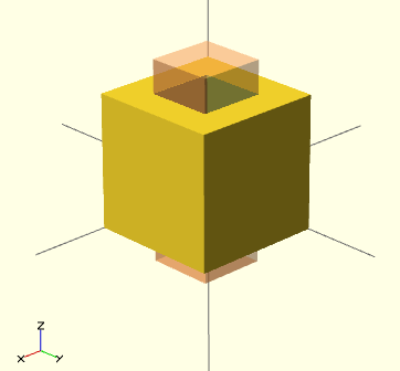
You always should make sure that the extracting object is "longer" or "shorter" than the object from which you carve out. Else you can run into "object is not 2-manifold problems" described in the troubleshooting section.
"Manifold" means that it is "water tight" and that there are no holes in the geometry. In a valid 2-manifold each edge must connect exactly two facets. That means that the program must be able to connect a face with an object. E.g. if you use a cube of height 10 to carve out something from a wider of cube of height 10, it is not clear to with cube the top or the bottom belongs. So make the small extracting cube a bit longer:
difference() {
	// original
	cube (size = [2,2,2]);
	// object that carves out
	# translate ([0.5,0.5,-0.5]) {
	    cube (size = [1,1,3]);
	}
}
Modifier characters - help for composing
So-called modifier characters allow you better see what is going on. If you put one of these before a subtree you can better understand what certain design elements do (this is particularly the case for union, intersection and difference operations.
- # Debug modifier
- The subtree will be rendered, but it also will be drawn in transparent pink
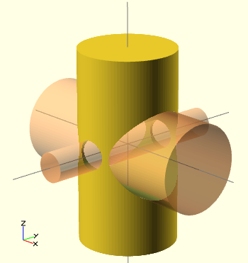
Example code:
difference() {
	// start objects
	cylinder (h = 4, r=1, center = true, $fn=100);
        // first object that will substracted
	# rotate ([90,0,0]) cylinder (h = 4, r=0.3, center = true, $fn=100);
        // second object that will be substracted
	# rotate ([0,90,0]) cylinder (h = 4, r=0.9, center = true, $fn=100);
}
- % Background modifier
- Show a subtree in the background. Objects will be shown in light gray and transformations applied, but the tree will not be rendered.
Example:
difference() {
	// start objects
	cylinder (h = 4, r=1, center = true, $fn=100);
        // first object that will substracted
	% rotate ([90,0,0]) cylinder (h = 4, r=0.3, center = true, $fn=100);
        // second object that will be substracted
	% rotate ([0,90,0]) cylinder (h = 4, r=0.9, center = true, $fn=100);
}
- ! Root modifier
Will ignore the rest of the design and use this subtree as design root. Useful to have a look a single element, without having to copy/paste it to a smaller test file. Usage example: ! { ... }
- * Disable Modifier
Simply ignores this entire subtree. Same function as commenting out with // Usage example:
{ ... }
2D geometry
Polygons
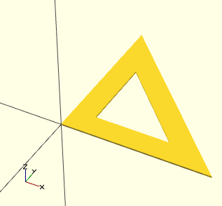
In this example, we have exactly 6 points (three for the "outer" triangle, and three for the "inner" one). Then, we connect each with two 2 path. In plain English, each element of a path must correspond to the position of a point defined in the points vector, e.g. "1" refers to [100,0].
2D to 3D extrusion
Example:
linear_extrude(height = 16, center = true, convexity = 10, twist = 0)
polygon(points=[[0,0],[100,0],[0,100],[15,15],[65,15],[15,65]], paths=[[0,1,2],[3,4,5]]);
Result: A 16mm high flat triangle with an empty triangle inside (figure needed)
Global dynamic variables
The $fa, $fs and $fn special variables control the number of facets used to generate an arc. You can override these in each module (i.e. more precisely they work with dynamic scoping)
- $fa is the angle of the fragments. It sets the minimum angle for a fragment. Even a huge circle does not have more fragments than 360 divided by this number. The default value is 12 (i.e. 30 fragments for a full circle).
- $fs is the size of the fragments and defines the minimum size of a fragment. Because of this variable very small circles have a smaller number of fragments then specified using $fa. The default value is 1.
- $fn is the number of fragments. I is usually 0. When this variable has a value greater than zero, the other two variables are ignored and full cirle is rendered using this number of fragments. The default value is 0.
When $fa and $fs are used to determine the number of fragments for a circle, then OpenSCAD will never use less than 5 fragments.
The shape of the circle can be improved by setting one of the special parameters $fn, $fs, and $fa.
Troubleshooting
Not simple objects
After compile and render GGAL (F6), you may see something like:
Parsing design (AST generation)...
Compiling design (CSG Tree generation)...
Compilation finished.
Rendering Polygon Mesh using CGAL...
Number of vertices currently in CGAL cache: 600
Number of objects currently in CGAL cache: 3
   Top level object is a 3D object:
   Simple:        '''no'''
   Valid:         yes
   Vertices:      200
Then when you try to export to .STL you get a message like:
Object isn't a valid 2-manifold! Modify your design..
In a valid 2-manifold each edge must connect extactly two facets. Here is a little example taken from the OpenSCAD Forum (retrieved 18:47, 22 March 2010 (UTC)):
	module example1() {
		cube([20, 20, 20]);
		translate([-20, -20, 0]) cube([20, 20, 20]);
		cube([50, 50, 5], center = true);
	}
	module example2() {
		cube([20.1, 20.1, 20]);
		translate([-20, -20, 0]) cube([20.1, 20.1, 20]);
		cube([50, 50, 5], center = true);
	}
The example1 module is not a valid 2-manifold because both cubes are charing one edge. They touch each other but do not intersect. Example2 is a valid 2-manifold because there is an intersection. Now the each edge must connect exactly two facets constraints of 2-manifolds is is met.
So, when performing composite solid geometry operations, it is important to remember that the piece you are subtracting must extend past the original part. (OpenSCAD Tip: Manifold Space and Time, retrieved 18:47, 22 March 2010 (UTC)).
Links
- Tutorials
- Front page of OpenScad has some good tips on constructive solid geometry (aka CSG)
- posts with label OpenSCAD on I Love Robotics]. The OpenSCAD Tip: Linear and Rotational Extrusions is a must read for beginners.
- Make: Projects - Simple 3D models with OpenSCAD. Explains how to create a "2D" 12 solid pentomino puzzle
- OpenSCAD Tip: Manifold Space and Time Read if you want to create water tight models.
- Other stuff
- Mashups (discussion on the BFB education forum)
- Parametric Duplo (mod by DKS on Thingyverse)
Credits and copyright modification
- Parts of this article were taken from OpenSCAD User Manual
- Note: Pictures I reused were originally mostly mine. Concurrently to writing this piece, I made updates to the manual on Wikibooks.
Links
- 3D modeling (Wikipedia)
- Polygon Mesh (Wikipedia)
- [http://en.wikipedia.org/wiki/Vertex_%28geometry%29 Vertex (Geometry, Wikipedia)
- Edge (geometry) (Wikipedia)
- Face (geometry) (Wikipedia).
- polyhedronl (Polyhedron)


