Adafruit Circuit Playground
There are TWO types of circuit playgrounds : one classic and one express. The classic version can run Arduino and Code.org and the express version can run MakeCode, CircuitPython, Arduino, and Code.org CS discoveries. We present here the Circuit playground Express
Introduction
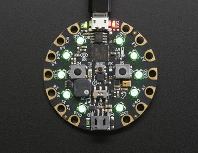
Circuit Playground Express (alias "CPX") is a board of the Adafruit Wearables line of of e-textile products. This board is beginner friendly since it can (also) be programmed with MakeCode and since it includes sensors, 10 LEDs, 2 push buttons, etc. and a loudspeaker in addition to the basic components (microcontroller, connectors, etc.). A new version, called Circuit Playground Bluefruit, includes Bluetooth and is under development, and as of Sept 2019 is in alpha testing.
The board is rather large and heavy compared to Adafruit's FLORA and GEMMA. However, this is compensated by it's feature rich design and ease of use.
- 50.6mm / ~2.0"
- Weight: 8.9g
The board can be bought in three packaging variants:
- Circuit Playground Express $25, includes just the board
- Circuit Playground Express - Base Kit, $30, includes a battery and USB cable.
- Circuit Playground Express Advanced Pack, $100, includes 2 Playground express, threads, needles, alligator clips, a servo motor, NeoPixels, etc.
For a class, it's probably best to buy Base Kits ($30), either a few Advanced Packs or other FLORA extension elements, and finally some simple boards (for replacements or projects that include more than one board).
Extras
See also:
- Adafruit Wearables (The e-textile line from which other elements like Adafruit NeoPixels, other sensors etc. can be picked and easily connected)
- Adafruit GEMMA (The tiny sister board)
- Adafruit NeoPixel (connecting and programming external Adafruit LEDs)
The board
Below is a picture of an Adafruit Circuit Playground Express
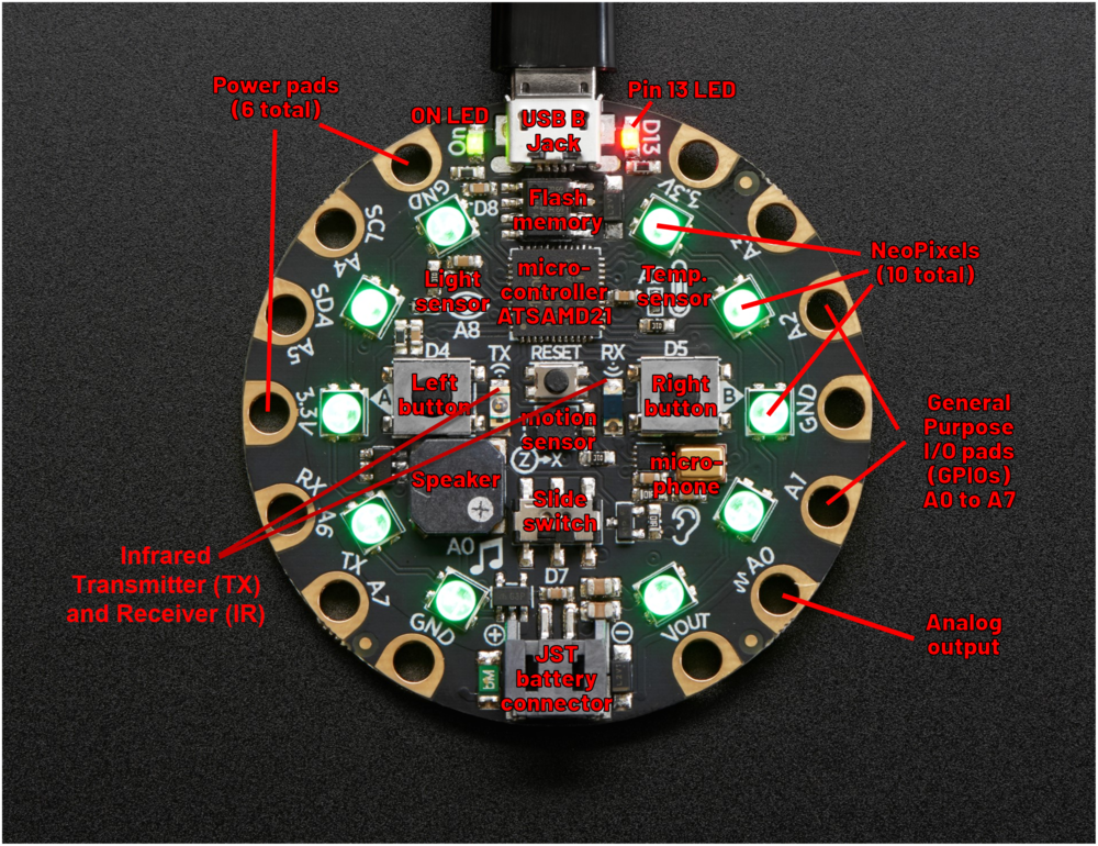
Components and layouts
According to the product page (retrieved Aug 26, 2019), this board includes the following elements which are explained in detail in the guided tour.
Processor and basics
- ATSAMD21 ARM Cortex M0 Processor, running at 3.3V and 48MHz
- 2 MB of SPI Flash storage (i.e. a tiny disk drive), used primarily with CircuitPython to store code and libraries.
- A JST battery connector (alternatively, the board also can take power from the USB connector).
- Green "ON" LED so you know its powered (top left)
- Red "#13" LED (D13) for basic blinking
- Reset button (in the middle)
- A total of 14 input/output pads ("the holes")
Connectivity
- MicroUSB port for programming and debugging. It can act like a serial port, keyboard, mouse, joystick or MIDI!
- Infrared receiver (D26) and transmitter (D25) - can receive and transmit any remote control codes, as well as send messages between Circuit Playground Expresses. Can also act as a proximity sensor.
- 14 "alligator" clip pads: a wide range of power pins, I2C, UART, Analog In, Digital In/Out, PWM, and Analog Out.
Output:
- 10 x mini NeoPixels (D8). These programmable LEDs can display any color. They are also used for some status information: when the bootloader is running they will turn green, or if it failed to initialize USB when connected to a computer, they will turn red).
- 1 Mini speaker (A0) with class D amplifier (7.5mm magnetic speaker/buzzer). It is connected to to the A0 analog output pin.
Input and sensors:
- 1 Temperature sensor (A9)
- 1 Light sensor (A8). Can also act as a color sensor and pulse sensor.
- 1 Sound sensor (MEMS microphone)
- 1 Motion sensor (D27), i.e. a LIS3DH triple-axis accelerometer with tap detection, free-fall detection.
- 2 x Push buttons, labeled A (D4) and B (D5)
- 1 x Slide switch (D7)
- 7 of the 8 GPIO pads have capacitive touch (A1, A2, A3, A4, A5, A6, A7)
Pads
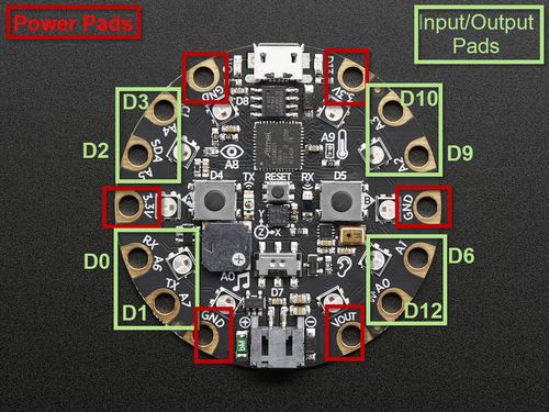
Below you wil find a picture whoch represent the main function of the pads (power pads OR General Purpose Input Ouput -GPIO- pads). The figure mentioned beside the pins are the a.k.a names of the GPIO pins with a "D". Indead, each GPIO pin have a surname (we have to figure out the utility of this surname but maybe it is for Arduino programming).
8 General Purpose Input Ouput (GPIO) pads (A0 to A7)
- Common for all pads
- ALL can be used as digital inputs, digital outputs, for LEDs, buttons, switches and also can be used as analog inputs (12-bit ADC).
- ALL can be used as hardware interrupt inputs.
- ALL (except A0) can be used for hardware capacitive touch.
- ALL (except A0 which is shared with the speaker) are completely "free" pins with no connections with other components and you are free by programming them.
- Each Pin :
- A0 (a.k.a D12) : special pin can be used as an analog output for reading audio clip for example. It can be digital I/O, or analog I/O, but if you do that it will interfere with the built-in speaker. This is the only put which cannot be used as capacitive touch.
- A1/D6, A2/D9, A3/D10 : pins can be digital I/O or analog input. These pins have PWM Output (Pulse With Modulation[1] Output) and can be capacitive touch sensor.
- A4/D3: pin can be digital I/O or analog input. This pin is also the I2C SCL (inter-Integrated Circuit Serial Clock line) pin and can be capacitive touch sensor.
- A5/D2: pin can be digital I/O or analog input. This pin is also the I2C SDA (inter-Integrated Circuit Serial Data Line) and ca be capacitive touch sensor.
- A6/D0 : pin can be digital I/O, or analog Input. This pin has PWM output, Serial Receive, and can be capacitive touch sensor
- A7/D1 - This pin can be digital I/O, or analog Input. This pin has PWM output, Serial Transmit, and can be capacitive touch sensor
Warning: Each pad can provide up to 20mA. Don't connect high power component such as servos, Neopixels ...
6 Power pads
- GND - 3 GROUND pads - interconnected using for signal / power ground connections.
- 3,3V - Two 3,3V output pads - used for small energy consumer components such as chips, sensors and lower power electronic components(i.e max electric intensity : 500 mA)
- VOUT - 1 VOLTAGE OUTPUT pad - it will be connnected either the UBS power or the battery input and it is used for servos, Neopixels, DotStard or other high power electronic components up to 5V (i.e max electric intensity : 500mA continuous or 1 Amp peak). It contains a resettable fuse and if the fuse trips, just wait 1 minute and it will be reset.
Packaging
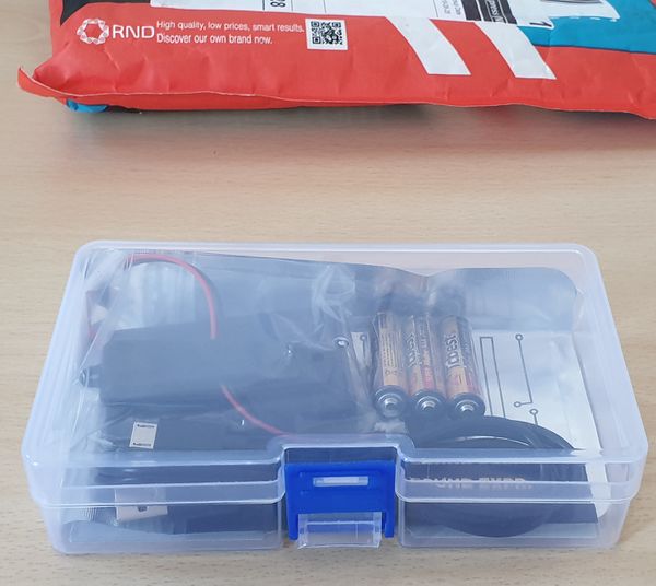
As explained above, the Circuit Playground Express is available as single component ($25), as basic kit (including a USB cable, needles, AAA-battery pack, lithium battery, and some thread, $30) and as Circuit Playground Express Advanced Pack ($100).
Add ons
Besides various Adafruit components that can be added, e.g. Neopixel strips, there are:
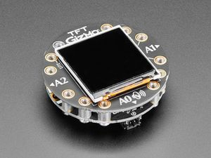
- Circuit Playground TFT Gizmo - Bolt-on Display + Audio Amplifier ($19.95). This "thing" can be bolted to a Playground Express. Quote: Once attached you'll get a 1.54" 240x240 IPS display with backlight control, two 3-pin STEMMA connectors for attaching NeoPixel strips or servos, and a Class D audio amplifier with a Molex PicoBlade connector that can plug one of our lil speakers. As of Stp. 2019, the product is sold, but still in alpha.
Programming the board
To compile and upload a program to the controller
- Open
- Connect the board with the USB cable
- Press the reset button in the middle(for a while). See the schema above if you cannot find it..
- When it turns green, you can download the code from your browser window.
Example
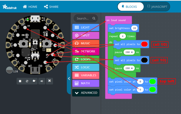
Javascript version
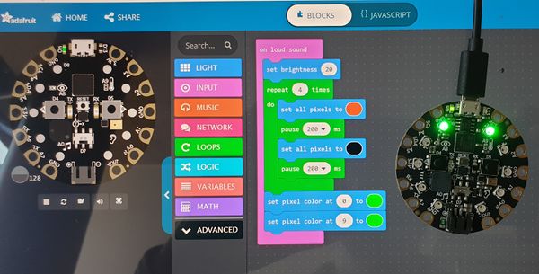
Notice how the RDG colors are defined. E.g. red (CSS #FF0000) becomes 0xff0000
input.onLoudSound(function () {
    light.setBrightness(20)
    for (let i = 0; i < 4; i++) {
        light.setAll(0xff0000)
        pause(200)
        light.setAll(0x000000)
        pause(200)
    }
    light.setPixelColor(0, 0x00ff00)
    light.setPixelColor(9, 0x00ff00)
})
Result after clapping
See also:
- MakeCode (includes other examples and more information about the language)
Links
Official tutorials
Adafruit Circuit Playground Express documentation
- Adafruit Circuit Playground Express (several pages)
- Adafruit Circuit Playground Express (in one HTML page)
- Adafruit Circuit Playground Express (all-in-one PDF file]
Tutorials
Many hands-on tutorials are available through the online editor, e.g. the clap lights tutorial (a simpler version of our clap hands example)
Hardware
- Adafruit pinouts (all details about pinouts, included a diagram)
Acknowledgement
Pictures as well as some text was reproduced from the Adafruit circuit playground express documentation. Some pictures are available under a CC BY-NC-SA license. Others are copyright AdaFruit and "all rights reserved" and reproduced with permission. Before you reuse any picture from this website, make sure to look at the license information.
For more information about using Adafruit, see https://learn.adafruit.com.
- ↑ Pulse width modulation allows to vary how much time the signal is high and low. It can be used to blink the led or make gradations of light
