Netfabb engine for RepRap
<pageby comments="false"/>
Introduction
Netfabb engine for RepRap creates machine code for RepRap-like 3D printers from *.STL and similar formats. Such software is sometimes called a "slicer". “The netfabb Engine for RepRap is a machine-specific software designed for 3D-printing with devices based on the RepRap principle. It is able to process any STL file and generates high quality toolpaths. It does not require any additional software. The [default] Engine includes a customized firmware for the BFB 3000 and the BFB RapMan, which allows accelerated moves during printing, machine control with a USB connection and direct data transfer.” (Engine for RepRap, retrieved May 10 2012)
Netfabb has other functionality like 3D mesh manipulation, mesh repair, and user interface with the printer. The slicer engine (Netfabb engine for fabbster) that we document here is included in the purchase of a fabbster 3D printer. So far it is not documented as such and since a fabbster is just a somewhat modified Mendel RepRap design, most functionality should be the same. Probably the only major difference with the Pro version that should work with all machines is the easy to understand USB control interface, machine settings, etc.
This little tutorial should be considered as a supplement of the more detailed Build Styles for netfabb Engine for RepRap and Material Settings for netfabb Engine for RepRap articles made in the netfabb wiki.
See also:
Calibration for dummies
Normal people like me can't print with default "balanced" and "detail" settings using ABS plastic rolls (as opposed to sticks). However, it is not very difficult to create profiles that create prints that are comparable to what most other 3D printers in this class can do. All you need to do is (a) to print with higher resolutions (aka layers) and (b) make sure that there are no very fine width/very slow combinations in the Build Style left. In other words, make sure that enough plastic comes all at all times.
Also: Make sure that your Plastic diameter is ok. It should be close to 3mm. 2.9mm can do, but 2.7 mm diameter (as in some rolls that we got with the prototype) hardly will work ! You can raise the temperature a bit for better flow.

Printing with very thin layers won't work well, since when the print head moves slowly and has to extrude with thin or fine width, extrusion rate (RPM) will become too low (between 2.5 and 5 rotations per minute) and the plastic won't come out anymore. It will get weak or favor creation of a "plug" (I don't know) and then nothing at even higher RPMs will come out at later stages. So let's work with bigger layers. This way we can make sure that we get at least 5 or RPMs. 0.25mm layers are quite ok for most needs.
It is difficult figuring out parameters that print well in small regions. The fabbster engine will by default in the "balanced" style slice a model according to three regions: big (> 4cm2), small (< 1cm2) and standard. Trouble with default settings happens usually in the "small" regions on outer borders that use slow speed and fine/thin width.
So let's create a new easy and simple Build Style that is inspired by the Balanced Style. It will define how big, standard and small regions are going to be printed and when. In addition, we will create a new Material setting that is adapted for 0.25 mm printing, i.e. we will redefine layer width, anti-stringing, as well as width and speed definition settings. A design will rely both on a build style and an associated material style.
The example parameters, we will use in this section closely resemble the Angelina style described further down.
Create a new Material Profile
So let's first create a new material that will print larger layers. We will define larger width definitions that should go with bigger layers. We also will deactivate anti-stringing for now since anti-stringing will reverse extrusion (pull in filament). This also does add to the trouble, however you may skip that option if you are optimistic.

- Make a copy of the Like ABS Blue material first and start from there. (Right-click -> Duplicate or click on Add Material)
- Select a good temperature, ca. 260-270 for ABS (but a bit lower also should do). Higher means better flow but less good overhangs. Too high (over 290) means trouble. Also ABS is not ABS. Some require higher temperatures than others ! E.g. right now I am using 265-275 for Fabbster Black ABS and less for Bits from Bytes ABS.
- Material settings: Layer Size = 0.250 (crucial !)
- Width: Set all Width between 400 and 1000.
- Speed: Set snake = 25mm/s
- Jumps: Set Travel RPM = 0. This may not be necessary, but negative extrusion can cause plastic to weaken. Since I managed to print with travel RPM = 3, you also could just reduce it a bit.

These settings will mainly eliminate the possibility to do very fine work. We will not aim at higher speeds that are used in "concept level" printing, therefore no need to change the higher speed settings.
Save when you are done
- Close the popup window
Create a new Build Style
Of course, you could keep a fairly complex build style, but I suggest to make it as simple as possible for your first attempt since less calibration work will result. Also, despite using a .250mm layer, "fine" print still may not work and we don't want any frustrations here. This is calibration for ordinary people like you and me.
Create a new BuildStyle first
- Style tab-> Manage build styles
- Add build style and use template Balanced or right-click on Balanced and make a duplicate. Remember, the idea is to create a design that looks pretty enough, but will not take ages to print. Therefore, "Balanced" is a good start.
- Click on Edit build style
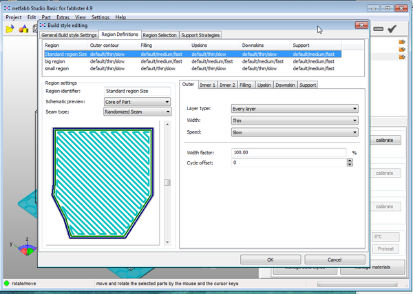
A radical solution looks like this: Set each region (per default you got three) to
- With/speed for elements that people will see: default/thin/slow for outer walls and roofs
- Width/speed for elements that are inside: default/medium/fast for all the Rest.
- Layer type: Change each to "Every layer", i.e. avoid "second" and "half layer". Typically, these can be found in "Inner 1, 2 and 3". Keep it as simple as possible. However, you could change back to "each second" in places, if something seems to become too fat.
- Keep the four wall parts: outer, inner 1, inner 2, inner3.
In the overview, "Default" means (probably) printing each layer. Makes sense, since they are bigger now. Later, you actually still can print half-layers. Don't for now !
Save when you are done
- Close the popup
Calibrate RPM with respect to speed/width
This procedure involves at least one step. Firstly you will have to guess what RPM you would need for the new layer size. Roughly speaking just add 60% to each and also make sure that none is below 10 ! By the way, if you do not understand what RPM means, remove the orange cover of the extruder and watch turning the wheels between 2.5 (very slow) and 120 (very fast) times per minute.

- Select your new Material (e.g. Green ABS Angelina Style)
- Press "Calibrate"
Now you are in the calibration assistant
- Now I suggest just calibrating for your new Build Style ! Later you then also can calibrate for a different material/build style combo
- Select your Build Style
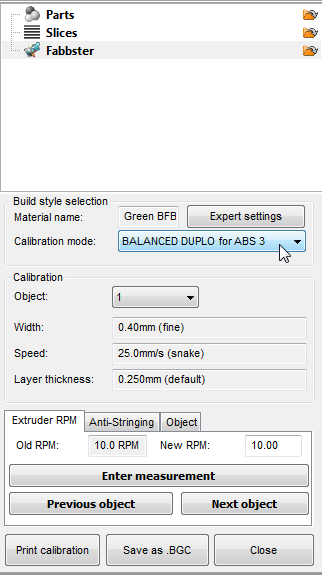
Now you will have to configure each Speed/Width combination, i.e. set an RPM and (optionally) remove the anti-stringing
- Add 50-60% to each RPM. Make sure that none is below 10
- Set New RPM
- In the Anti-stringing tab, set pullback to 0
- Set New pullback
- Then Click on Next Object or select it from the pulldown menu
As you can see, there will be few objects to calibrate (e.g. about 6). The reason is that we simplified the build style. Later, have a look the official Netfabb Relaxed style and you can see that there more speed/width combinations. If you don't select a build style you will get even more.
Test with a small print
- If the result is ok, you are done
- If it is not, then you can reflect and adjust Material + Build Style and then again check/adjust RPMs. A better alternative is using the Netfabb calibration assistance explained in the next step.
Netfabb calibration assistant
- Check if the print head can go to the back and the right back corner ! It must be close but not touch. If it touches it will burn the platform and your plastic will be stuck again in the extruder (we don't care about the platform, but about the extrusion) !!
- Press "Print Calibration". I now must print, else you didn't do what I said above (no RPM below 10 !!!)
- With a Caliper measure each wall. You can buy a cheap caliper (20 Euros or less) in a do-it-yourself store or online
- Report the width for each calibration object (i.e. the speed/width combos you just defined)

- You will notice that RPMs will change, probably go lower
- Make sure that none is below 10 RPM (but you decide what your printer can handle)
Test with a small print
- If the result is not ok, then you must change your build style (sorry) or just lower your ambitions. * If you change Build Style, e.g. add a new combination of speed/width, then please check the calibrations again. You may have a freaky element, e.g. (snake/thin) that does 2.5 RPM that you must adjust !
- Also, remember what we said about the plastic. If its diameter is lower than 2.9mm you might consider buying another roll. Before you do so, find a segment in the roll where it is thicker and try again. The wheels must be able to push it down.
- If the result is ok, you now can stop or read on and do some further tweaking ....
Further work
- Temperature
- Lower temperature by 3-5 degrees and try if plastic still comes out at low RPM. Lower is better (creates better overhangs)
- Manual RPM adjustments
- Manually adjust RPMs if you like in the calibration. E.g. if you think that medium/fast produced strings that are too fat, just lower a bit.
In addition, you also could upper/lower region width in the build styles or even boost head speed and RPM in the USB Controls/Override tab, but I argue against. While we aim to print at higher resolution, this "lower quality" must look good ! Just use the overrides for testing, but don't make it a habit !
- Anti-stringing
Activate anti-stringing measures again, your result now requires that you have to remove strings, with a little knife and/or with some burning.
- Contour offsets
- If you build flat roofs, then you may have to use negative distances to the contours. I.e. when the print head moves over an empty space, it should hit the contour so that the plastic will stick
Anti-stringing calibration
Anti-stringing is important if your object has a lot of details that stick out. Have a look at a fabbster default material and use these settings or divide these by 2. I settled for -3 RPM in most of my material settings. But sometimes I had to turn anti-stringing off (printing tiny objects at very low speed).
Note on burning away small strings: ABS can and will burn for real. Buy a micro-burner, e.g. a Dremel and keep the distance ! Also flip-flap objects back and forth or they will warp starting at fairly low temperatures (60 degrees ?)
In picture below, you can see Duplos with strings: left is after full calibration, right is after some manual changes as described above:

In the next picture, DUPLOS are without strings, i.e. printed with the Angelina style that you can download.


Contour offsets and overlap with filling
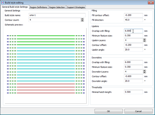
As we said above, you may have to adjust distance between walls (contours) and upskins, downskins and filling.
For example, if you build flat roofs like in a Duplo block, then you may have to use negative distances to the contours. I.e. when the print head moves over an empty space, it should hit the wall hard so that the plastic will stick. Else the plastic may just fall down or worse create knots and mess up your print. For DUPLOS, I use about -0.6mm. That's a lot, but it can't be helped.

If you want to get Duplos right, the most important parameter to change is Overlap with filling. Set it to 6mm and read more in Dealing with flat roofs
Simple build styles and material styles
Read:
- Netfabb engine for fabbster build styles (moved ...)
Build style and material style principles
under construction right now - 16:43, 22 May 2012 (CEST)
Material styles
Material styles define many parameters that are related to three most important filament deposition parameters:
- extrusion speed (RPM, rotations per minute) defines how much plastic comes out. Extrusion speed can be either positive (very little to lots) or negative (i.e. pulls filament back in)
- head movement speed, defines how fast the print head will move while extruding or while traveling without extrusion.
- layer size (how much the print head will move up in the z-direction after printing a layer)
- temperature (including cooling or waiting)
That may sound simple, but it is not. There are countless combinations of these parameters, and within a print different combinations will be used.
For starters, the most important question is how much plastic is going to be deposited at what speed and temperature. The second most important question is what is going to happen when the print head moves without printing.
How much plastic ?
In Netfabb, material output is not defined by some combination of head movement speed and RPM as in some other slicers. The software added two abstraction layers, i.e. width and speed. This allows to configure a print with the same amount of plastic at different speeds. Faster for coarser prints, slower for more difficult prints.
To get this working you first must define a series of three parameters. After that, you can fine tune (calibrate) the RPM using a different tool !
Material and Build styles go together. I.e. you can't think of a build style that uses 0.25 layers and then use an original 0.15mm Netfabb Material definition.
1. Layer size
Layer size defines how much the print head will move up after printing a layer. Actually, Netfabb requires that you think about three layer sizes:
- The default (normal) layer is set at 0.15mm. Compared to other similar 3D printers, this is fairly small and leads (in principle) to high quality prints. However, if you work with plastic roles, this layer size is too small since no plastic will come out if you print fine "strings" at very low speed. This is the reason why we decided to use a 0.25mm default layer.
- Half layers are half of that. To be use for rendering of small difficult parts. The printer simply will (roughly) slow down RPM by half and then move up by a half step and then print an other half layer on top.
- Double layers are double. The printer first will print other normal and half layers and then print double layers.

2. Width
In the Width section you must define six values from fine to fat. These values are purely theoretical, i.e. in principle you must print out calibration objects and adjust flow, i.e. RPM later.
The default fabbster width definitions are the following:
| name | default size |
|---|---|
| fine | 0.4mm |
| thin | 0.5mm |
| medium | 0.7mm |
| Strong | 0.9mm |
| Fat | 1.0mm |
This is actually quite surprising, since the smallest layer size is less than 0.1mm. In other words, we expected that "fine" could have a been a bit finer. The reason for printing larger than higher is that when you put squeeze on layers, they will become more solid. However, we did not test yet what happens with half layers and do not trust this very much. In any case, for our own 0.25mm we mostly used the exact same definitions, meaning that we prefer to print in a less dense way.
3. Speed
Speed will define print quality. Unlike in other slicers where the user must figure out what happens at a given speed/RPM combination, the result in terms of thickness with fast/medium and slow/medium should be the same.
The default fabbster speed definitions are fairly spaced out. In our Vanessa styles we preferred to narrow the steps between snake and medium.
| name | default speed | Vanessa speed |
|---|---|---|
| snake | 25 mm/s | 25 |
| slow | 50 mm/s | 40 |
| medium | 70 mm/s | 60 |
| fast | 80 mm/s | 80 |
| Ultra | 120 mm/s | 120 |
Calibration
If you define new layer sizes and change width and speed definitions, we suggest to calibrate.
(For now, see above)
Overrides
There are two kinds of overrides:
(1) In the toolpath tab you can change both speed and extrusion rate (RPM). This a useful tool for testing major changes you should make in the Material definitions, or for adapting a build style made for another kind of object. Otherwise, don't use it, now that you know how to create build styles ....
(2) In the expert Manage build style settings, one can adjust a spread factor (called width factor) for each region component, e.g. upskins, downskins, outer, inner1. You can use this setting for certain types of objects. E.g. if your material definitions work just fine for pillars but not for upskins you can make a quick adjustment here. Alternatively, diminuish or augment the width.

As of version 1.4.9, "less" means more and the other way round. E.g. if your upskin is too fat at 100%, then set it at 120%....

Build styles
Region definitions
You can define styles for various "regions". Where and how you are going to use these regions is a different issue. Typically, you would print small regions at lower speed and bigger regions with higher speeds.
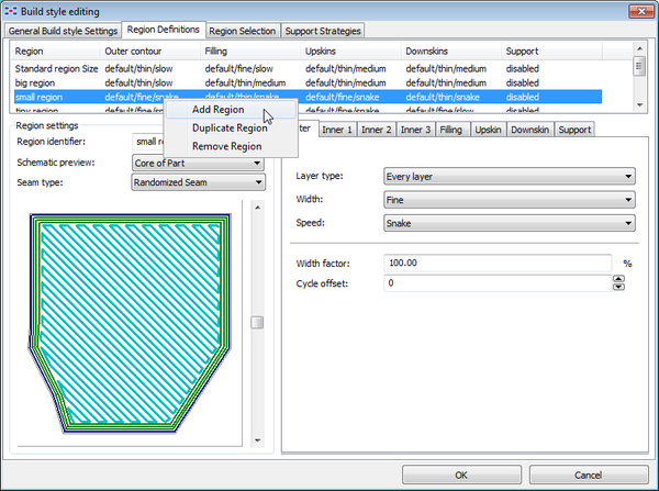
To add or duplicate a region, right-click on a region in the upper panel:
What is a region
It is important to understand that a region is a horizontal slice. It is not something that is defined by a contour (although such regions could be implemented in the future).

Region selection
Region selection is probably the most difficult issue to understand. You can activate use of a region under three different conditions. Regions then can be combined in a tree.
Before you start using the region selection, you must think about your regions and add them in the "General Build style settings".
Then got to Region Definitions an now be careful:
- First select the tree element that you want to define, e.g. the root element or a sub-element
- Then only select either by contour length, area or by layer !
So let's shortly look at the three types of region selectors:
By layers
This is typically used to define what happens in the first 2 layers. For some objects, it is better to print more slowly and maybe with some higher width (but check how little RPM you can handle !).
This method requires you to enter at least one threshold value, e.g. "2"
By area
In many build styles that are made for little objects, one area is enough. In other words, you would print everything fairly slowly in order to get good quality. If you apply this principle to bigger objects, then you can easily wait 10 hours vs. 2-3 hours to get a print done.
Therefore it is a good idea to define at least three variants:
- small regions that need fine printing
- normal regions that can be printed faster
- big regions that can be printed fast.
However, this principle only can work if your "normal" and "big" regions are simple.
This method requires you to enter at least one threshold value, e.g. "1cm2". Tip: Since an area is defined by the surface of the whole slice, it often is pointless to define tiny regions. Rather make sure that both the tiny part and the larger not so tiny parts in the same slice print well.
By contour length
Same principle as above, except that the contour is taken as measure of size. E.g. a 1cm x 1cm square would have a contour of 40mm and a 2cm x 0.5cm rectangle a contour of 5cm. Using cm2 areas is probably simpler to understand and makes more sense in most cases.
You can build very complex trees. However, most people rather would defined several build styles, i.e. on build style per type of object. For example, one for simple DUPLO bricks, one for RepRap parts, one for artistic objects and so forth.
A typical pattern is the following:
- First two layers
- Rest
- small regions
- Normal regions
- Big regions
As shown in the following pictures, you will have to define threshold values for both the first "layer" node and then for the "third" Select by Area node.
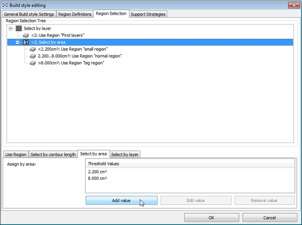
Once you defined threshold values, you then can associate a region for each threshold.

Again, I strongly suggest that you think before you click, or you will loose all your definitions:
- First select the element in the tree that you want to configure
- Then, click at the bottom ! Also, select the right element, do not experiment (unless you do it just for learning ....)
Tips and tricks
Dealing with flat roofs
Default build styles cannot deal with flat "roofs", i.e. the kind that you would find in DUPLO blocks. Dealing with this problem is fairly simple and involves three steps:
In the Build Style
(1) Set Overlap with filling higher, e.g. 6mm
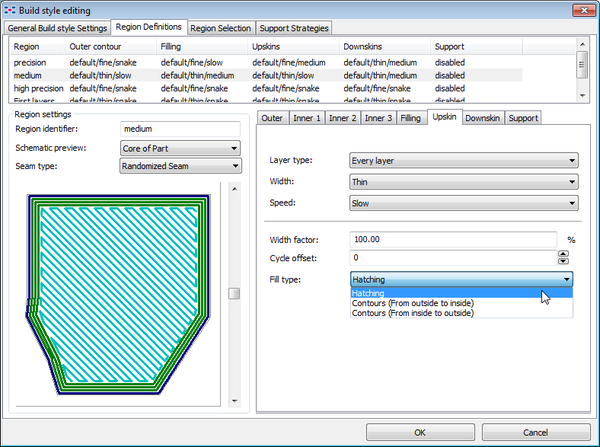
(2) Use hatching !
For each region definition, change the upskins and downskins to use straight lines
Turn the model
Flat upskins and downskins are printed left-to-right (along the x-axis and the y-axis). By turning the model you will achieve much better results.

Dealing with small and high objects
Frequent symptoms: Plastic will stay weak and bend sideways.
Solutions:
- Print as "cold" as you can, however you may have to try more than once finding the minimal temperature.
- Put another object next to it, e.g. a double. This way the plastic will cool before the next layer starts. Alternatively, try putting a cylinder around an object. You then can lower travel speed a bit, but not too low (see next item)
- If you print at slow speeds (10RPM), this strategy may fail, since plastic can stop coming out after the print head travels. Setting anti-stringing to zero and raising temperature will help.
- Use a hairdryer or a ventilator that can blow cold wind. In that case, you may have to raise temperature a bit (not tested).
- Set minimal layer time to something like 5 seconds. Remove anti-stringing and raise temperature if needed. I got much better results with the printing two objects in a row trick, but I maybe didn't try enough ....

Printing with PLA
I tried to print with translucid PLA and so far I didn't manage, except for a little "flat" and dense heart.
What I think so far:
Starting up:
- Don't print a raft, but I am not sure about this. A fat traditional raft may actually help getting it flow (help this with pushing it down).
- Remove the filament, then when the extruder goes up for heating insert it with RPM = very fast. If you leave the filament inside during the warmup and after printing it will clog the nozzle, i.e. expand in the square and then it can't be pushed down anymore
Expert settings:
- Lower head speed by half (snake = 10, ultra = 60)
- Aim for medium RPM (whatever that means, got to test first)
- Double all the width in the same way. I.e. make sure that z-steps are low, print fatter than you would with ABS. PLA must touch.
Anti-warping designs
- Try using holes
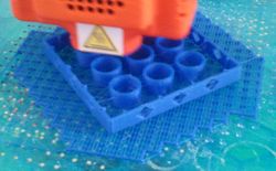
- Print a flat 0.5mm circle (and the cut if off) Source: Someone in the fabbster forum
(more later)
See how-to-3dprint-large-objects-without-warping.html
Links
- At Netfabb - Wiki pages
- Engine for RepRap. This is the menu page.
- Netfabb Engine for RepRap Machine Settings, explains basic settings and the interface with 3D printers.
- Calibration of Engine for RepRap. Calibration allows to detect what your machine can do, an alternative to thinking and trying out.
- Material Settings for netfabb Engine for RepRap. Actually more than Material settings. Explains how to configure basic parameters (temp, speed, layer size etc. for a material profile(
- Build Styles for netfabb Engine for RepRap. Most important reading, since it explains how one can configure Netfabb to deal with different sorts of parts. There is some extra information about current settings, but as of May 18 not very well detailed:
- Predefined Predefined build styles for Netfabb 4.9.1
- Tune the Buildstyles
- At Netfabb - forums