Static SVG tutorial
<pageby nominor="false" comments="false"/>
This article or section is currently under construction
In principle, someone is working on it and there should be a better version in a not so distant future.
If you want to modify this page, please discuss it with the person working on it (see the "history")
automatically translated from french .... please wait a day -15:11, 3 April 2012 (CEST)
Introduction
This short tutorial aims to introduce static SVG 1.1.
See also
- Article SVG (read first)
- SVG interactive tutorial and animated with SMIL (continued)
- Interactive tutorial and animated SVG DOM (cont'd)
Each SVG file has the following structure:
- XML declaration
- A root SVG with a declaration of the namespace (namespace)
- The DTD is not mandatory (just useful to edit with some XML editors)
 <svg xmlns="http://www.w3.org/2000/svg">
 ......
 </ Svg>
Often an SVG file contains internal links. In this case, it is also necessary to define the namespace xlink. The example below defines the size of the canvas as SVG, which is optional but highly recommended.
 <svg xmlns="http://www.w3.org/2000/svg" xmlns:xlink="http://www.w3.org/1999/xlink"
      width="600" height="300">
 ......
 </svg>
When using HTML and SVG in XHTML, similar rules apply. See the examples below.
Examples SVG awareness
The following example shows a simple SVG graph used by the server as an SVG file. In 2010, almost all browsers can view it. If you must use IE, take version 9 (beta winter 2011).
<?xml version="1.0" standalone="no"?>
<!DOCTYPE svg PUBLIC "-//W3C//DTD SVG 1.0//EN"
         "http://www.w3.org/TR/2001/REC-SVG-20010904/DTD/svg10.dtd">
 <svg xmlns="http://www.w3.org/2000/svg">

  <!-- un petit rectangle avec des coins arrondis  -->
  <rect x="50" y="50" rx="5" ry="5" width="300" height="100"
        style="fill:#CCCCFF;stroke:#000099"/>

  <!-- un texte au meme endroit -->
  <text x="55" y="90" style="stroke:#000099;fill:#000099;font-size:24;">
   HELLO cher visiteur
  </text>
 </svg>
File: http://tecfa.unige.ch/guides/svg/ex/svg-intro/hello-svg.svg
Embedding SVG in XHTML and HTML5
- See SVG (XHtml) and Using SVG with HTML5 tutorial
Overview of graphic elements and attributes
Each graphic element is represented by an XML element. These elements:
- are configurable with XML attributes
- inherit attributes from their parents (eg. a fill color).
As in other languages vector (eg. VRML), there are basic geometric shapes (rectangle, ellipse, circle, lines, poly-lines and polygons). Then there are elements to produce complex shapes.
Listed below are the most important elements:
- Rectangles <rect>
- The circle <circle> and the ellipse <ellipse>
- Lines <line> and political lines <polyline>
- Polygons <polygon>
- With arbitrary shapes <path>
- Images <image>
- Text
Most elements share a common number of attributes such as the "id" attribute (identifier)or "style" (CSS2 styles). Most attribute values are quite intuitive to those who are a bit familiar with CSS. Others, such as the path element require some learning since they include some kind of "sub language"
- Positioning: The SVG objects are positioned in a coordinate system that begins in the upper left (S standard practice in computer graphics). It is possible to work with local coordinates
- Transformations: Each object can be translated, directed and changed size. It inherits the transformations of the parent object.
- Style: SVG defines dozens of attributes, properties for certain elements. Regarding the graphics, these are the two most important:
stroke, defines how the edge (line) of an object is rendered.fill, defines how to render the fill of an object.
SVG has two different syntaxes for defining the properties of an element:
- The style attribute uses the syntax and CSS2 styles. We can define these styles in an external file. In other words, it's the same logic as for HTML.
- There are also presentation attributes SVG, it simplifies the generation of SVG content with XSLT and makes the code slightly more readable.
Example: SVG Presentation Attributes
<rect x="200" y="100" width="60" height="30"
      fill="red" stroke="blue" stroke-width="3" />
have the same effect as a type declaration in a CSS2 style attribute:
<rect x="200" y="200" width="60" height="30"
      style="fill:red;stroke:blue;stroke-width:3" >
View property index of the SVG specification for more information.
Styles "CSS" or XML attributes ?
- Advantage of CSS: you can transfer your knowledge of CSS / HTML
- Advantage of the XML attributes: easier to generate with XSLT, PhP etc..
Examples:
(1) Method CSS
 <rect x="50" y="50" rx="5" ry="5" width="300" height="100"
       style="fill:#CCCCFF;stroke:#000099"/>
 <text x="55" y="90" style="stroke:#000099;fill:#000099;font-size:24;">
(2) Method XML attributes
 <rect x="50" y="50" rx="5" ry="5" width="300" height="100"
       fill="#CCCCFF" stroke="#000099"/>

 <text x="55" y="90" stroke="#000099" fill="#000099" font-size="24">
SVG shapes
Rectangles <rect>
Sets of rectangles including rounded corners. Below we introduce the most important attributes:
x = "coordonné" et y = "coordonné"
x and y indicate the position of the top left, clockwise direction and the lower canveas
Examples:
x = "15" y = "15mm"
Default: x and y are 0, the default units are inherited by the parent or are pixels.
width = "<longeur>" et height = "<longeur>"
define the size of the rectangle
Examples:
width = "100"
height = "100"
rx = "length" et ry = "length"
X and y axis of the ellipse used to round, no negative number can not exceed the respective lengths of moist
Examples:
rx = "5"
ry = "5"
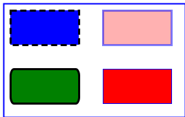
Rectangles with style:
<?xml version="1.0" standalone="no"?>
<!DOCTYPE svg PUBLIC "-//W3C//DTD SVG 1.0//EN"
         "http://www.w3.org/TR/2001/REC-SVG-20010904/DTD/svg10.dtd">
<svg width="270" height="170" xmlns="http://www.w3.org/2000/svg">
 <title>Some rectangles with differents fills, strokes and opacities</title>

 <rect x="5" y="5" width="265" height="165"
       style="fill:none;stroke:blue;stroke-width:2" />

 <rect x="15" y="15" width="100" height="50"
       fill="blue" stroke="black" stroke-width="3" stroke-dasharray="9 5"/>

 <rect x="15" y="100" width="100" height="50"
       fill="green" stroke="black" stroke-width="3" rx="5" ry="10"/>

 <rect x="150" y="15" width="100" height="50"
       fill="red" stroke="blue" stroke-opacity="0.5" fill-opacity="0.3" stroke-width="3"/>

 <rect x="150" y="100" width="100" height="50"
       style="fill:red;stroke:blue;stroke-width:1"/>
</svg>
The circle and the ellipse <circle> <ellipse>
cx = "coordonné" et cy = "coordonné"
cy = "10" cy = "20"
define the position of the center ("c" = circle)
r = "longeur"
r = "10"
defines the radius of the circle
rx = "longeur" et ry = "longeur"
rx = "10" ry = "20"
defines the radius of x and y axes of the ellipse ("r" = radius)
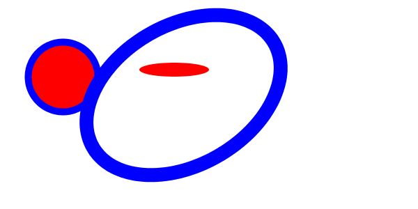
For instance:
<?xml version="1.0" standalone="no"?>
<!DOCTYPE svg PUBLIC "-//W3C//DTD SVG 1.0//EN"
          "http://www.w3.org/TR/2001/PR-SVG-20010719/DTD/svg10.dtd">
<svg width="600" height="300"
     xmlns="http://www.w3.org/2000/svg">

 <title>Circles and ellipses </title>

 <circle cx="90" cy="110" r="50"
        fill="red" stroke="blue" stroke-width="10"  />

  <ellipse cx="250" cy="100" rx="50" ry="10" fill="red" />

  <ellipse cx="160" cy="250" transform="rotate(-30)"
        rx="150" ry="100"
        fill="none" stroke="blue" stroke-width="20"  />
</svg>
Lines <line>
x1 = "coordinate" et y1 = "coordinate"
Starting point
x1 = "100" y1 = "300"
x2 = "coordinate" et y2 = "coordinate"
Point of arrival
x2 = "300" y2 = "500"
poly-lines <polyline>
points = "10,100,10,120,20,20, ........"
Sets of points x, y that are linked
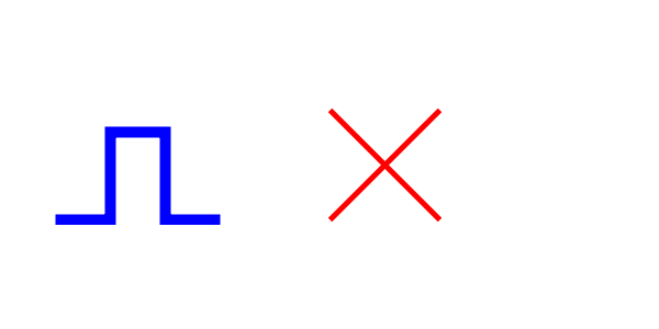
Sample lines and polylines
<?xml version="1.0" standalone="no"?>
<!DOCTYPE svg PUBLIC "-//W3C//DTD SVG 1.0//EN"
         "http://www.w3.org/TR/2001/REC-SVG-20010904/DTD/svg10.dtd">
<svg width="600" height="300"
     xmlns="http://www.w3.org/2000/svg">

 <title>Lines and polylines </title>

 <polyline fill="none" stroke="blue" stroke-width="10"
	   points="50,200,100,200,100,120,150,120,150,200,200,200"  />

 <line x1="300" y1="200" x2="400" y2="100"
       stroke = "red" stroke-width="5"  />

 <line x1="300" y1="100" x2="400" y2="200"
       stroke = "red" stroke-width="5"  />
</svg>
Polygons
A polygon is a closed shape, its edge is a polyline "closed"
points = "chemin de points"
points = "10,100,10,120,20,20, ........"
Series of points x, y which will be linked (also the last to the first point)
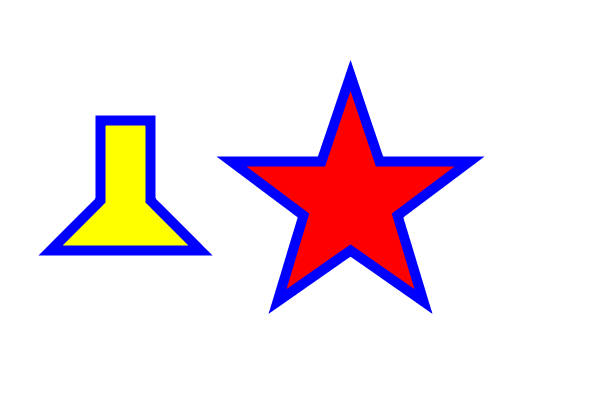
For instance:
<?xml version="1.0" standalone="no"?>
<!DOCTYPE svg PUBLIC "-//W3C//DTD SVG 1.0//EN"
         "http://www.w3.org/TR/2001/REC-SVG-20010904/DTD/svg10.dtd">
<svg width="600" height="400"
     xmlns="http://www.w3.org/2000/svg">

 <title>Polygones </title>
 <desc>The red star was stolen from the SVG spec</desc>

 <polygon fill="yellow" stroke="blue" stroke-width="10"
	   points="50,250,100,200,100,120,150,120,150,200,200,250"  />


 <polygon fill="red" stroke="blue" stroke-width="10"
	  points="350,75  379,161 469,161 397,215
	  423,301 350,250 277,301 303,215
	  231,161 321,161" />
</svg>
With arbitrary shapes <path>
The element <path> can define arbitrary shapes (shapes). They can have an outline (stroke) and be used as a "clipping path".
d = "path data"
- d = "M 100 100 L 300 100 L 200 300 z"
- d = "M100, 100 L300, 100 200.300 z" (same command)
"Path data" is a fairly complex building which we will present only an excerpt below
Note the syntax for the "path data": You may insert commas and newlines when we want, we can eliminate the white space between a command (letter) and totaled below.
Commands "path data" base:
d = M et m
M and m are the "moveto" commands. You have to imagine that the pencil is repositioning without drawing. M indicates absolute coordinates, m relative coordinates from the starting point. An M always opens a "subpath" (see also the Z command).
M | m (xy) +
M100 100 200 200
d = L et l
L and draw lines to the current point (s) point (s) (s) indicated. It thus resembles the instruction polyline
The | l
The 200.300 100.200
d = Z et z
Z and z close the current subpath. In other words, draw a line from the current point to the beginning of the path (defined with a M or m)
Z | z
d = H et h, V et v
draw the vertical and horizontal lines.
h100
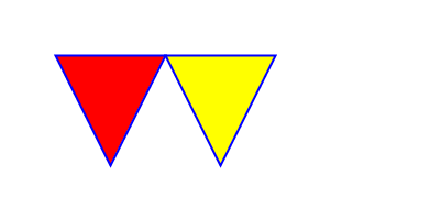
Example of a simple path:
The following code draws two triangles red and yellow with a blue border.
<?xml version="1.0" standalone="no"?>
<!DOCTYPE svg PUBLIC "-//W3C//DTD SVG 1.0//EN"
  "http://www.w3.org/TR/2001/REC-SVG-20010904/DTD/svg10.dtd">
<svg width="400" height="200" xmlns="http://www.w3.org/2000/svg">

 <title>Example triangle - simple example of a 'path'</title>

 <path d="M 50 50 L 100 150 150 50 z"
       fill="red" stroke="blue" stroke-width="2" />

 <polygon points="150 50 200 150 250 50"
       fill="yellow" stroke="blue" stroke-width="2" />
</svg>
- We put the pencil (
M 50 100), then we draw a line towards the bottom corner (L 100 100) and towards the top right corner (150 100),finally is closed (z). - Note that the yellow triangle (similar) was done with <polygon>
d = C et c, S et s
For drawing with Bezier curves
d = Q et q, T et t
Quadratic Bezier curves
d = A et a
- Syntax: A
| A (rx ry x-axis-rotation large-arc-flag sweep-flag xy) +
Elliptical arc (elliptical or pieces of a circle when rx = ry):
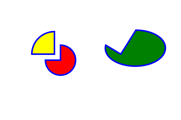
Example of a cake:
From yellow to
- it is positioned at 180, 180 (
M 180,180) - we draw a vertical line y = -75 (
v-75). BECOME This starting point for the arc. - one draws an arc (
a) with radius 75 and radius x = y = 75 (75,75), without rotation (0). The second0indicates the arc is on the side "small", the third0indicates a negative direction of drawing. The-75,75indicate the arrival of the arc. - everything is closed (
z)
<Path d = "M200, 200 h a50-50, 0 50 1.0 50 -50 z"
fill = "red" stroke = "blue" stroke-width = "5" />
The red hand is the same logic:
- one draws the arc in the same direction (negative), but the side "large" (
1) implicitly defines the angle of the departure, the radius and the arrival.
Still below the code for the green to the right
<! - Some baking :) That Has Gone Wrong ->
<Path d = "M400, 180 L350, 150 a100, 100 1.0 60 0, -50 z"
fill = "green" stroke = "blue" stroke-width = "5" />
The text
- The support text to SVG 1.0 is quite poor, in SVG 1.1 and SVG 1.2 there is good support. It was found the same trend in Flash ...
- Each 'text' element causes the rendering of a single text string.
- A text is a graphic object as another: One can apply the transformation functions of coordinate system, painting, trimming and masking and a CSS style.
<text x="55" y="90" style="stroke:#000099;fill:#000099;font-size:18;">
- A default text is displayed on a line, but you can also make the perimeter of a 'path' element.
tspan:
To display text on multiple lines with SVG 1.0, you must pre-compute the line breaks and use a single 'text' element with one or more children 'tspan' and the appropriate values for attributes x, y, dx and dy
<text x="55" y="90" style="stroke:#000099;fill:#000099;font-size:18;">
Hello. Let's show: <tspan x="55" dy="20"> a blue rectangle that pops up and goes
again</tspan> <tspan x="55" dy="40">and a yellow that slowly arrives and then stays!</
tspan> </text>
text, tspan et textPath
<?xml version="1.0" encoding="ISO-8859-1" standalone="no"?>
<!DOCTYPE svg PUBLIC "-//W3C//DTD SVG 1.0//EN"
          "http://www.w3.org/TR/2001/REC-SVG-20010904/DTD/svg10.dtd">

 <svg width="12cm" height="3.6cm" viewBox="0 0 1000 300"
  xmlns="http://www.w3.org/2000/svg" xmlns:xlink="http://www.w3.org/1999/xlink">
 <title>Exemple toap02 de http://www.yoyodesign.org/doc/w3c/svg1/text.html, pris le 8 Mars 2005</title>

 <defs>
  <path id="MonTrace"
   d="M 100 200
   C 200 100 300   0 400 100
   C 500 200 600 300 700 200
   C 800 100 900 100 900 100" />
 </defs>
 <desc>Exemple toap02 - un 'tspan' dans un 'textPath'</desc>

 <use xlink:href="#MonTrace" fill="none" stroke="red"  />
 <text font-family="Verdana" font-size="42.5" fill="blue" >
  <textPath xlink:href="#MonTrace">
   En
   <tspan dy="-30" fill="red" >
    haut
   </tspan>
   <tspan dy="30">
    ,
   </tspan>
   puis en bas, et encore en haut
  </textPath>
 </text>

 <!-- Montre le contour du canvevas avec un élément 'rect' -->
 <rect x="1" y="1" width="998" height="298"
  fill="none" stroke="blue" stroke-width="2" />
 </svg>
File: http://www.yoyodesign.org/doc/w3c/svg1/text.html (original)
Links
SVG allows to make connections to other resources (URLs). The tag <a> </ a> delimits the sensitive area. In the following example the green rectangle and the text
- the link is indicated with an XLink attribute (xlink: href = "....")
- Warning: You must declare the namespace for XLink
Example - Links to other resources with the beacon
<?xml version="1.0" encoding="ISO-8859-1" standalone="no"?>
<!DOCTYPE svg PUBLIC "-//W3C//DTD SVG 20010904//EN"
  "http://www.w3.org/TR/2001/REC-SVG-20010904/DTD/svg10.dtd">
<svg height="900" width="900"
  xmlns:xlink="http://www.w3.org/1999/xlink"
  xmlns="http://www.w3.org/2000/svg">

  <desc>Un lien se crée simplement avec la balise a.</desc>

  <a xlink:href="http://tecfa.unige.ch">
    <rect style="fill:#00FF00;stroke:#00FF00" width="300" height="40" ry="5" rx="5" y="80" x="50"/>
    <text x="100" y="110" style="stroke:#000099;fill:#000099;fontsize:24;">TECFA POWER 1 click away</text>
  </a>
</svg>
Structuring: Grouping elements and references
Each high-level computer language must allow to group objects into blocks, to name and reuse. SVG has several interesting buildings. It is also interesting to note that SVG objects (such as HTML objects) inherit the style of their parents! In other words, the styles are "cascading".
Listed below are the most important elements. Note that you must refer to the specification for full attributes of these elements. Here, we show that a small sample!
- The fragment of an SVG document: <svg>
- Grouping of elements with <g>
- Abstract objects (sets) <symbol>
- Definition section <defs>
- Use of elements <use>
- Title and Description <title> <desc>
The fragment of an SVG document: <svg>
<svg>is the root of a SVG graph- We can embed SVG elements among others and position
- Each <svg> creates a new coordinate system. Thus we can easily reuse fragments graphics without having to change coordinates
- See also: Using a viewport (below)
Hello SVG Example 2
<?xml version="1.0" standalone="no"?>
<!DOCTYPE svg PUBLIC "-//W3C//DTD SVG 1.0//EN"
          "http://www.w3.org/TR/2001/PR-SVG-20010719/DTD/svg10.dtd">
<svg xmlns="http://www.w3.org/2000/svg">

 <!-- un petit rectangle avec des coins arroundis  -->
 <rect x="50" y="50" rx="5" ry="5" width="200" height="100"
       style="fill:#CCCCFF;stroke:#000099"/>

 <!-- un texte au meme endroit -->
 <text x="55" y="90" style="stroke:#000099;fill:#000099;font-size:14;">
  HELLO cher visiteur
 </text>
 <svg with="200" height="200" x="200" y="100">
  <!-- un petit rectangle avec des coins arroundis  -->
  <rect x="50" y="50" rx="5" ry="5" width="200" height="100"
	style="fill:#CCCCFF;stroke:#000099"/>

  <!-- un texte au meme endroit -->
  <text x="55" y="90" style="stroke:#000099;fill:#000099;font-size:14;">
   HELLO cher visiteur
  </text>

 </svg>
</svg>
Grouping of elements with <g>
The <g> element is used to group elements "go together":
- Children inherit the properties <g>
- We document a group (for example help search engines to index) and with <title> <desc>
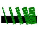
Example - A simple group of bamboo
<?xml version="1.0" standalone="no"?>
<!DOCTYPE svg PUBLIC "-//W3C//DTD SVG 1.0//EN"
         "http://www.w3.org/TR/2001/REC-SVG-20010904/DTD/svg10.dtd">
<svg width="200" height="200"
     xmlns="http://www.w3.org/2000/svg">

 <g stroke="green" stroke-dasharray="9 1" >
  <title content="structured text">Mon plus beau dessin
  </title>
  <line x1="5" y1="80" x2="155" y2="80" stroke-width="30"
	stroke="black" stroke-dasharray="none" />
  <line x1="10" y1="30" x2="30" y2="100" stroke-width="5" />
  <line x1="40" y1="30" x2="60" y2="100" stroke-width="10" />
  <line x1="70" y1="30" x2="90" y2="100" stroke-width="15" />
  <line x1="100" y1="30" x2="120" y2="100" stroke-width="20" />
  <line x1="130" y1="30" x2="140" y2="100" stroke-width="25" />
 </g>
</svg>
- Note how the color green and the "dashing"
stroke-dasharray="9 1"are inherited. - Against the black line by using "overrides", for example stroke = "
black"
Abstract objects (sets) <symbol>
- <symbol> defines a graphical object with reusable <use>
- <symbol> <g> resembles, except that the object itself is not drawn
- <symbol> has attributes viewBox and preserveAspectRatio more
 <symbol id="bleublancrouge">
 <rect x="0"  fill="blue" width="10" height="10"/>
 <rect x="10" fill="white" width="10" height="10"/>
 <rect x="20" fill="red" width="10" height="10"/>
 <rect x="0"  fill="none" width="30" height="10" stroke="black"/>
 </symbol>
See the use of use element below
Definition section <defs>
- <defs> <symbol> somewhat resembles, but is simpler
- Anything inside <defs> is set but not drawn.
- Can be used arbitrarily each element that has an identity
<defs>
<rect id="redsquare" fill="red" width="10" height="10"/>
<rect id="yellowsquare" fill="yellow" width="10" height="10"/>
</ Defs>
See the use of use element below
(Re) using elements with <use>
- <use> can reuse the following items: <svg>, <symbol>, <g>, graphics elements and <use>
- <use> behaves slightly differently depending on the type of object sets (see the specification
!):
- It is therefore a basic tool to avoid repeating code.
Reusable objects:
- Each element is desired reuse must have an identifier XML
<rect id="redsquare" fill="red" width="10" height="10"/>
xlink is defined by the standard XLink (not SVG). Therefore, do remember to set its namespace (normally it is done already at the root of SVGP)
<svg width="10cm" height="3.5cm" viewBox="0 0 100 30"
      xmlns="http://www.w3.org/2000/svg"
      xmlns:xlink="http://www.w3.org/1999/xlink">
Important attributes:
- x, y, with, height can reposition and resize the object
- xlink: href to reference and instantiate the object (with its "id" attribute)
Example - Reuse of a rectangle
<?xml version="1.0" standalone="no"?>
<!DOCTYPE svg PUBLIC "-//W3C//DTD SVG 1.0//EN"
  "http://www.w3.org/TR/2001/REC-SVG-20010904/DTD/svg10.dtd">
<svg width="10cm" height="3.5cm" viewBox="0 0 100 30"
     xmlns="http://www.w3.org/2000/svg"
     xmlns:xlink="http://www.w3.org/1999/xlink">
 <desc>Reuilisation d'un rectangle</desc>
 <rect id="MyRect" width="60" height="10"/>
 <use x="20" y="10" fill="yellow" xlink:href="#MyRect" />
 <use x="20" y="20" fill="red" xlink:href="#MyRect" />
</svg>
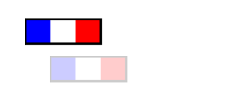
Example - Using an object <symbol>
<?xml version="1.0" standalone="no"?>

<!DOCTYPE svg PUBLIC "-//W3C//DTD SVG 1.0//EN"
  "http://www.w3.org/TR/2001/REC-SVG-20010904/DTD/svg10.dtd">

<svg width="10cm" height="3.5cm" viewBox="0 0 100 30"
     xmlns="http://www.w3.org/2000/svg" xmlns:xlink="http://www.w3.org/1999/xlink">
 <desc>Utilisation d'un dessing bleau blanc rouge</desc>
 <symbol id="bleublancrouge">
  <rect x="0" fill="blue" width="10" height="10"/>
  <rect x="10" fill="white" width="10" height="10"/>
  <rect x="20" fill="red" width="10" height="10"/>
  <rect x="0" fill="none" width="30" height="10" stroke="black"/>
 </symbol>

 <use x="10" y="5" xlink:href="#bleublancrouge" />
 <use x="20" y="20"  xlink:href="#bleublancrouge" opacity="0.2"/>
</svg>
Example - Using defs
The Spanish colors are more cheerful than that of France :)
Title and Description <title> <desc>
<title> <desc> and to document the code. These elements are not displayed as is, by against a client may decide to display them as "tooltips" for example
2 for reasons well documented:
- Better understand the code
- Help the user (to explore ...)
- Help search engines index your SVG (SVG is text
!)
Elements that can have <title> and <desc>
- Containers ('svg', 'g', 'defs' 'symbol', 'clipPath', 'mask', 'pattern', 'marker', 'a' and 'switch')
- graphic elements ('path', 'text', 'rect', 'circle', 'ellipse', 'line', 'polyline', 'polygon', 'image' and 'use')
Images <image>
- Bitmap formats supported: jpeg and png
- <image> also inserts a file svg (with a new viewport)
Important attributes:
x = "coordinate" et y = "coordinate"
defines the location (as <rect>, <svg>, <g>, etc..)
width = "longeur" et height = "longeur"
defined height and width of the image (as <rect>, <svg>, <g>, etc..)
Positive values indicate the size to display
(Note: a value of 0 prevents the display, negative values are allowed)
xlink:href = "uri"
sets the URI where the image
Adjusting the size of the image
- See preserveAspectRatio and in viewBox coordinate system, transformations and units (below)
- An image is displayed by default according to the dimensions you give
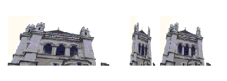
Including an image in several ways
<?xml version="1.0" encoding="ISO-8859-1" standalone="no"?>
<!DOCTYPE svg PUBLIC "-//W3C//DTD SVG 1.0//EN"
  "http://www.w3.org/TR/2001/REC-SVG-20010904/DTD/svg10.dtd">
<svg width="500" height="200"
     xmlns="http://www.w3.org/2000/svg" xmlns:xlink="http://www.w3.org/1999/xlink">
 <desc>Inclusion d'une image externe. Normalement un client doit
       implémenter l'importation de png, jpeg, et svg.
 </desc>

 <image x="10" y="50" width="200" height="100" xlink:href="cathedrale_ge.jpg">
  <title>Eglise large</title>
 </image>

 <image x="250" y="50" width="50" height="100" xlink:href="cathedrale_ge.jpg">
  <title>Eglise longue</title>
 </image>

 <image x="310" y="50" width="100" height="100" xlink:href="cathedrale_ge.jpg"
	preserveAspectRatio="xMinYMin meet">
  <title>Eglise juste</title>
 </image>

</svg>
Coordinate system transformations and units
Canvas, viewports and units
SVG canvas
- The canvas SVG is an infinite space or displays SVG content
The SVG viewport
- The "viewport" SVG the rectangle is visible to the user
- The viewport has a coordinate system that starts at the top left of the rectangle (viewport coordinate system, also called viewport space)
- We can define a viewport with an element that defines an example with the element <svg>
- The drawings are made relative to coordinate system user (user coordinate system or user space) that initially when the client displays the image "is identical to the viewpoint coordinate system
- Some clients allow the user to move and "zoom" the "user space" (Alt-drag to move the Adobe plugin)
- Any design that exceeds the viewport is truncated (clipped)
Lengths
- The lengths are specified either by number or by the absolute or relative standard units:
- em, ex (width of "m" and height of an "x" on the current font)
- px (pixel units defined by the device)
- pt, pc (points, and?). Normally the client indicates how many pixels corresponds pt, or pc, similar to the cm, mm and in.
- cm, mm, in
- percentages (based on the viewport)
- Direct service numbers without units is drawn in relation to the units used to set the viewport (pixels by default)
- Note: You can choose to ignore the subtleties of the system of lengths, but the next task should be mastered and re-read the specification.
Creation of viewports
Elements that create a new viewport
- <svg>, <symbol> (instantiated by <use>) <image>
- and <foreignObject> (eg an image in the future X3D)
The viewBox
(See explanations in one day, it is not clear at all .... sorry)
- All the elements that create a new viewport + <marker>, and <pattern> <view> can adapt the dimensions of a graphic to those of a suitable container
viewBox = "<min-x> <min-y> <width> <height>"
Caution: Do not use anything other than just numbers! 1500 and therefore not 15mm or 150px!
Examples:
<svg width="300px" height="200px" viewBox="0 0 1500 1000">
<svg width="300px" height="200px" viewBox="0,0,1500,1000">
- viewBox can graft a coordinate system on the actual dimensions of a viewport.
- This is very useful when such drawings in meters and which must anyway be displayed on the screen.
- You can also create distortions (where width and height of the viewBox are not the same proportions as those of the viewport).
Resizing a drawing office with ViewPort
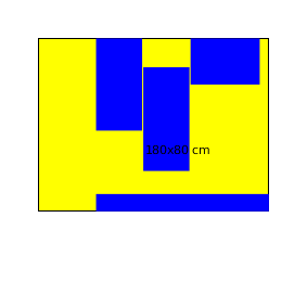
Warning: The images *. Png generated by the wiki is wrong. You must see the svg (click it 2 times ...)
The preserveAspectRatio:
This is available when attibut Noveau when viewport is created and used to indicate how to preserve the ratios (x, y) in the drawing.
preserveAspectRatio = "<align> [<meetOrSlice>]"
The parameter "align":
There are full of different kinds of align. This parameter indicates what should happen when the relationship between length and height of the viewBox does not match the viewBox, in other words: like "draw" graphics.
- none - Tire graphics with two edges
- xMinYMin - alignment and x-min y-min (top left corner)
- xMinYMid - alignment and centering x-min y-
- xMinYMax-alignment and x-min y-max (bottom left corner)
- ... and the other six combinations between x * and Y *.
The parameter "meetOrSlice"
- meet (default) - keep the "aspect ratio", the entire viewBox is visible and is suitable for drawing, graphise will always be visible but may be using it all the viewport.
- slice - keep the "aspect ratio", the viewBox use it all the viewport and may exceed one way (according to "align"), ie there will be cut graphics.
Caution: Observe case sensitive!
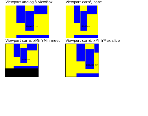
Example: Adaptations of an office in the ViewPort
- This example shows some variation of "preserveAspectRatio compared to viewBox that do not have the same ratios as the viewports
- In the specification there are more details and examples
- Be careful to write the settings correctly, your client may not complain for such errors
Transformations with the attribute "transform"
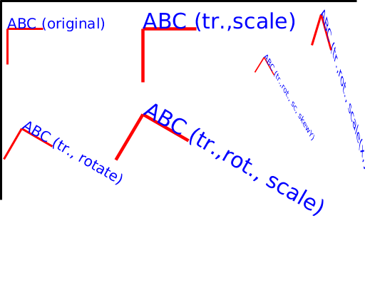
- transform is used to define translations, scalings, rotations, transformations in a matrix, and skewX skewY
Translations with the "translate"
- We have already seen that it is possible to define a new coordinate system with the new viewport and viewBox
- The attribute "transform" available for all container elements and graphics (see [SVG-intro-html.html # 46752 Graphics base] and [SVG-intro-html.html # 51310 Structure: Grouping elements and references] ) also permits.
translate (<tx> [<ty>])
For instance:
<g transform="translate(50,50)">
Resizing (scaling) with the parameter "scale"
scale (<sx> [<sy>])
where sy is not specified it is assumed that y = sx
Examples:
<g transform="scale(2)"> <rect .... /> <g>
<g transform="scale(2,3)"> <rect .... /> <g>
Rotations with the "rotate"
rotate (<rotate-angle> [<cx> <cy>])
- The rotation angle in degrees
- cx and cy define the center of rotation (by default it is as the beginning of the local coordinate system, NOT the center of the object
!)
Order of operations
The order of operations is sequential (so it must be read from right to left in these examples)! At each transformation we obtain a new coordinate system! The following two fragments are the same thing:
 <g transform="translate(-10,-20) scale(2) rotate(45 translate(5,10)">
 <! - Elements graphics go here ->
 </g>
<g transform="translate(-10,-20)">
  <g transform="scale(2)">
     <g transform="rotate(45)">
        <g transform="translate(5,10)">
 <!-- Graphic elements go here -->
 </g> </g> </g> </g>
Simple transformations
- It is not always easy to imaging that provides a series of transformations (remember VRML? )
- The matrix transform operations allow more general (and harder to understand, see the spec.).
Next steps
- Dynamic SVG (animations)
- Interactive SVG
- SVG generation
There are two types of dynamic SVG
(1) Animation with "SMIL" tags
- Only works with newer browsers (2011) except IE9 or with a very old plugin from Adobe
- See the SVG/SMIL animation tutorial
(2) Animation with JavaScript and DOM
- ... is more powerful (you can do anything), but more difficult
- works with all current browsers
Interactive SVG
- requires a little bit of ECMAScript if the rest is done with SMIL tags
- can require a lot of ECMAScript if everything is done through DOM programming
SVG generation
- Server-side generation of static SVG is easy. It can be done with any scripting language.
