RapMan
This article or section is currently under construction
In principle, someone is working on it and there should be a better version in a not so distant future.
If you want to modify this page, please discuss it with the person working on it (see the "history")
Introduction
RapMan is a commercial kit of the RepRap 3D printer. “RepRap is short for Replicating Rapid-prototyper since it was developed in a research project on self-replicating machines.
This 3D printer builds the parts up in layers of plastic with the help of a custom-made Thermoplast Extruder. The machine takes a 3mm diameter filament of a polymer, forces it down a heated barrel, and then extrudes it as a melt out of a fine nozzle. The resulting thin stream is laid down in layers to form the parts that RepRap makes. The extruder should work up to a temperature of 260 degrees Celsius. It works with various polymers like ABS (Lego-like plastic) and polylactic acid. The extruder can move left/right (X axis) and forward/backward (Y axis) The printed object sits on a platform that will move down (Z axis)
Printing instructions are written in a language called G-code. A user will copy a g-code file to an SD card. This card is then inserted into a slot of the RapMan board for printing.
This article has two functions:
- It's a meta manual for Rapman version 3.1: We will try to explain how RapMan works in order to help the reader understanding stages of assembly and we will point out to the most important manuals and other information sources you should read
- We will add some missing points and report some difficulties.
Parts, manuals and workspace
.
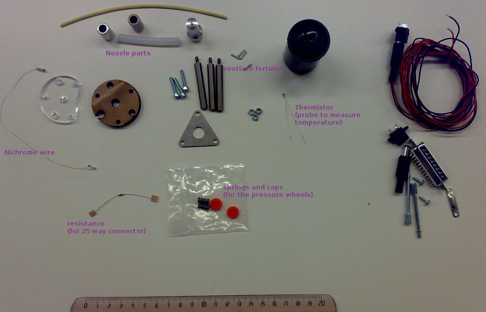
When we ordered a RepRap it came in a fairly small plastic-wrapped cardboard box. In addition, we got some boxes with polymer filaments (6 ABS rolls and some others ...). To the left is a picture.
You may check the insides of the boxes. E.g. compare contents to the list that you can find in each of the three following manuals, i.e. in the "included" section in the begging.
- Build manual (for the "cartesian robot")
- Extruder manual
- Hot End manual (pink cables were missing from both the 3.1 version and in our case in the delivered kit)
Finally, there may be faulty pieces. In our case the holes in the base bed (page 51 of the build manual) were not straight. Other folks in the forum reported this problem. IMHO ours were sort of straight enough. The setup, i.e. a bolt with spring that ties down the print bed is used to micro-adjust the level of the print bed in 3 dimensions (see the operations manual).
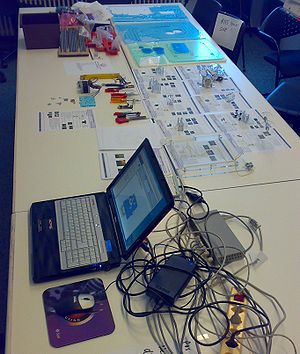
It's easier to reserve a lot of space for assembly. At TECFA, we used our seminar room and took about 2 x 6 meters :). See picture to the right.
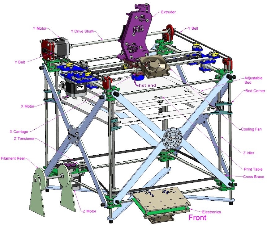
Now, keep the following picture from the build manual in mind. This is what you are going to build. The most important parts are labeled (we added the hot end, i.e. part of the extruder that will heat the plastic filament).
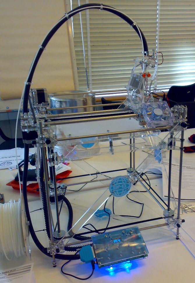
You also should look a real picture, below is ours:
Overview of the manuals
All manuals are available at Bits from Bytes. At the time of writing (feb 2010) they could be found in the downloads section. The "build info" section includes outdated version. So, in any case, always make sure that you get the manuals for the version you ordered, e.g. RapMan 3.1. Here is a list of the manuals:
- Build Manual - Printed: This manual explains how to assemble the so-called cartesian robot. This refers to the printer (including the motors and the belts that will move the extruder in the X/Y axis and the plate up/down (Z-axis). In other words, it's all that's mechanical, except the extruder.
- 3D Build Manual part 1: As above but include 3D models that you can view in PDF. Click on a "picture" to enter 3D mode. Make sure to install the latest PDF version and to use a PC with a decent graphics card. Also, explore the Acrobat menu to the left. You can add-remove parts for better visibility.
- 3D Build Manual Part 2: As above, part 2. Also includes writing of the motors and the controller.
- Animated Build Manual: As above, but includes animations. We didn't use this manual.
- Build Manual Videos: This manual includes three videos that show how to build some of the more difficult parts.
- Extruder Manual: Explains how to assemble the extruder, i.e. the print head that will be moved around in X/Y directions by the "cartesian robot". It will pull in the plastic filament and feed it into the so-called attached hot end which you somewhere during the assembly process. Finally it also explains how to wire the extruder to the controller.
- Hot End Manual: Explains how to assemble the hot end. The hot end will heat the plastic. It's a bit tricky to assemble, since you have to wrap a heating wire around, attach a temperature probe and cover with fire cement in several stages.
- Operations Manual: Explains how to calibrate and use the printer. In particular: calibrate the print head, update the firmware, use the controller interface and print files.
Notice: In some case, the newer version did not have enough information to understand the process. E.g. we looked at some 3.0 version manuals where procedures are explained in more detail. However, this information needed to be adapted, because some parts are not the same and generally speaking 3.1 is easier, in particular assembling the hot end !
As of Feb 2010, the build manual is quite superb (with little mistakes), the extruder manual is ok enough, since at this stage you can build without reading .... The hot end manual is not good enough (yet).
Tools
Then you will have to buy tools. All except two can be easily found in a do-it-yourself store. Read: V3Info.pdf (this file may not sit next to the build manual). Dictionary (terms are in UK English):
- A spanner is called Wrench in US English, "clef à écrous" en français
- Allen key is a "hex key" or "hex head wrench"
- A Needle file is a small abrasive file.
(1) Easy to find tools:
- 4mm Spanner 1
- 5.5mm Spanner 1
- 8mm Spanner 1
- 13mm Spanner 2
- 1.5mm Ball End Allen Key 1 (it's important to get ball ended keys, since sometimes you will "come in diagonally". We suggest to buy quality tools, because of easier fit).
- 2.5mm Ball End Allen Key 1
- 4mm Ball End Allen Key 1
- 2mm Flat Blade Screw Driver 1 (get a good one, this is need for attaching wires to the board)
- Tape Measure 1
- Soldering Iron 1
- 1/2 Round Needle File 1 (we actually suggest to buy several ones including a square-shaped one. Since these are used by modeling fans you can get handful of various shapes for about 5 to 15 Euros (depending on quality). We got the cheap ones.
- Wire Cutters 1 (maybe not needed, since a stripper also can cut)
- Wire Strippers
(2) Difficult to find tools:
- A good multimeter that can measure small resistance. Not difficult to find actually, but my not be found in a supermarket. We didn't test resistances as we should have ... ;)
- A 1/16'' Allen key. We found it w/o problem in a hardware store that sells to professionals
(3) Extra tools (not mentioned in the bills of tools)
- You might acquire a key that can measure a small torque pressure (the typical thing you get in a do-it-yourself shop is just good for the nuts on car wheels). This is an expensive professional tool. We didn't get one. (see practice run)
- At least two Pliers. One should be long and flat. Useful for holding nuts in place before you use the keys. Cheap ones will do.
- A small (!) tube of super glue. I broke the extruder wheel (the only thing we broke) and fixed it with super glue :)
- A hammer. You are allowed to use it only once though :(
- Various meters, i.e. a long flat 2 meters for measuring cables and a small metal one (preferably one whose end starts at zero, else a plastic office-type one can also do). The latter one is to measure distances in the assembly and for selecting bolts.
- A (no bigger than 2GB) standard SD card. It will be inserted into the board to print files.
The assembly procedure
Practice run and parts terminology
The practice run has three important functions:
(1) You will learn how much you can tighten the screws. The golden rule is simple: really ringer tight then add 1/2 turn with a key.
(2) Terminology: Although we do understand English, we didn't know about these:
- A washer is a "flat disk" (rondelle in french)
Also remember to look at the "big picture" on top for terminology of the rapman parts.
(3) Learn how to read the manual. You quickly will learn about the names of nuts and bolts:
The cartesian robot
The cartesian robot is fairly easy to build if you understand English and are used to read computer manuals for example. I takes about 2-3 full days (2 persons working on it).
Things that will go wrong:
- Some pieces may be assembled in a wrong way. Make sure to pay attention to "asymmetric" pieces.
- Again: Do not over-tighten. Plexy glass can shatter quickly.
- Geometry. If you do it right, most everything should be "cubic", i.e. distances and 90 degree angles. If you get that wrong, the printer will not work properly ....
The extruder and hot end
The extruder and the hot end is described in different manuals plus in the PDF with videos.
The extruder manual explains how to assemble the mechanical parts of the Extruder. This part is fairly easy.
The hot end manual is not clear enough:
- The manual includes instructions for two different versions of the kit, i.e. insulated vs. non-insulated nichrome. Nichrome is a resistance wire that will heat. It's the kind of wire you may find in a toaster.
- The parts you get are not the same as the ones described in the manual. E.g. the kit already included a non-isolated nichrome with the bootlace ferrules attached (i.e. step 9 on page 5 already was completed in the kit I got).
The nozzle assembly (part one) is easy. The tricky part is wrapping the nichrome, fire cementing it, adding the thermistor and fire cement again.
Here is what we did:
- Attach the nichrome to cables (as explained). You have to attach wires with the ferrules and squeeze these with a plier, then slide the yellow head-proof sleeves over it (in the manual, explained before nozzle assemble)
- Put a small layer of fire cement around the aluminum nozzle
- Make sure that the wires will be on the side of the hole of the MDF !
- Wrap the nichrome around (make sure they don't touch)
- Add fire cement (be careful not to smear anything inside the nozzle hole or the thermistor hole), then wait 12h
- Add the thermistor (this is a bit tricky since you'll have to add fire cement.
- Then cook with the ventilator outlets (as explained in the manual)
- Then add more fire cement to make it look pretty.
- Cook again (actually much longer than they say)
Since we didn't have a good enough multimeter, we didn't test anything after it. If we made it wrong, we'd have to order a new hot end kit anyhow ...
Test printing and tuning
Last minute checks and trouble shooting
Check the following (we all of these wrong in some ways)
(1) Alignment of the X and Y axis
- Alignment of the X and Y axis is crucial. If badly aligned then a circle may print as ugly sort of square. This happened to us, because we took the Y belts away to check the motor.
(2) Belt tensions
- Make sure all three are tight
(3) Z belt tension and alignment
- Make sure that the end of the rods, i.e. the ball bearings sit in their casings (rebates). File these again if necessary. If you don't the Z axis will be misaligned (or you hear noisy clicks, because the belt will not be aligned properly)
(4) Extruder
- That was my huge mistake: I attached the pressure wheels in the wrong way. The side where the wheels stick out should be toward the extruder. Else it won't move the wire. Big frustration after you try to print the test pattern :(
- Make sure that is nicely attached. At some point I remove the extruder to check the nozzle and forgot to tighten 2 screws. Result was a skewed print.
(5) Attached wires
- Even if you did attach the wires to the board and the 25 way pin as told, they may become loose. E.g. in our case the red wire for the Y motor became loose on the board and the motor would just crank a little bit forward and backward. We thought that it would be a too tight Y Drive shaft, disassembled this one and the wound up with misaligned Y belts, i.e. the the X carriage wasn't aligned anymore with the Y(0) end...
(6) Search for loose nuts and bolts (also after printing a few test objects)
Calibrating
Rough alignment of the print bed:
- Align the bed horizontally with respect to the Z axis. I.e. remove the Z belt and turn the rods
- Keep the print head at a safe distance, e.g. 0.5 cm and move it around. Then go closer until you are more or less satisfied.
Copy the Control Interface page of the operation manual and over-line the important manual move mode commands.
Then move around in all three axis. If a motor won't work, check wirings. If you hear strange noises, check alignments and belt tension.
Fine tuning of the print bed alignment
Adjust the print bed with bolts. This is a bit tricky and needs several iterations. In each position, the nozzle should be about 0.5 mm away. We used five sheets of 70mg paper (500 sheets = 5cm) to do this.
Go slowly !
Test extruding
Make sure that you sander the print bed. Remove the dust, e.g. you can easily remove it, sand it, the wash it. The principle is that the filament has to stick.
Use manual mode, i.e. Tool setup
- Put the print head in position over the hole (front side, right)
- Up the temperature to 245-250 degrees: Press +/- Y
- Up the extrusion rate to 5mm/s(econd) = 10 RPM: Press +/- X
Then, as soon as the bolt in the extruder starts turning (temperature reached):
- Push in the filamenent
- Tighten the two screws (red caps)
- Paint a dot on the filament to check if it goes down ... If it does not tighten, if the motor blocks or if it jumps, loosen
- Print at least half a meter
Printing the test pattern
(1) Upgrade the firmware as explained in the operations manual. To do so you need:
- A small to normal USB cable
- The HIDBootLoader.exe application
- The firmware, e.g. file RapMan2_0_8.hex (as of Feb 2010)
(2) Then print the test raft pattern.
- Copy file 'TestRa.bfb to the SD card
- Insert in the board and print ...
(3) Repair the TestRa.bfb file to make it fit your situation. Most likely temperatures are too low (see G-code below).
First print
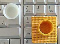
Then print the cup (it may take several attemps to get it right). In the pictures are our second (white) and fourth (yellow) attemps. You also can see the raft made for the yellow version.
Both cups are not yet satisfactory. Some tuning ahead - 15:12, 28 February 2010 (UTC).
Note: The Extruder-Fan doesnt run all the time. It is not needed for ABS.
- In Gcode, it can be turned on/off: M106 - fan on, M107 - fan off.
Printing
If you use ABS plastic (by default you like do) then you must understand the following:
- You should first print a raft at a somewhat lower temperature (else it will stick to the print bed)
- Then, the object will be printed on top.
The three print parameters
It is important to understand that printing will be affected by three parameters:
- Temperature
- Extrusion speed (how fast the bolt turns in the extruder)
- Head movement speed
In addition:
- Pressure on the extruder's pressure wheels. They have to be fairly tight.
These all interact somewhat and that makes calibration difficult.
Temperatures for ABS
White ABS:
- Raft temperature: 235 (or a bit more)
- Print temperature: 240-245 (or a bit more)
Color ABS:
- Raft temperature: 235 (or a bit more)
- Print temperature 243-248 (or a bit more)
It is likely that may need to adjust temperatures to your setting. We think that it may be because the thermistor may not be exactly where it should be (how could you check under the cement ...), wiring may be different (length of resistances), etc.
You can manually adjust temperatures during printing, but you may have to react quite quickly. Also there may be a problem with transport of the filament (e.g. temperature is hot enough, but plastic is not coming in...)
Extrusion speed and pressure wheels on the extruder
- To see if the plastic moves down I painted small dots on the wire.
- Tighten quite a lot (without forcing of course). If the filament does not move, add pressure.
- Until you got it all sorted out, I recommend putting the print head in position (x max and y min, e.g. over the hole that is diagonally opposite from home). Then manually extrude about half a meter of filament at the temperature you set in the G-code file. See if flows as advertised ...
G-code
3d model into G-Code
Skeinforge is a tool chain composed of Python scripts that converts your 3d model into G-Code instructions for Rapman.
- Download: Skeinforge
- Read Skeinforge
In education
See Teaching Resources (BitsforBytes Wiki)
Links
Research Reprap 3D printer
- RepRap, a British project, is short for Replicating Rapid-prototyper. This 3D printer builds the parts up in layers of plastics. It can be assembled from parts bought in various places.
- RepRap Project (Wikipedia)
- Introduction to Reprap, retrieved 24 June 2009.
- RepRap Official Blog
- Spare parts: See reprapsource. German company that sells spare parts.
BitsfromBytes RepRap
- Bits from Bytes. Sells RepRap kits (£750 / CHF 1270).
- This web site also includes a forum an a wiki.
- Thing to make (Rapman wiki)
- thingyverse.

