Adafruit Circuit Playground: Difference between revisions
| Line 75: | Line 75: | ||
==== Programming the board ==== | ==== Programming the board ==== | ||
'''To computile and upload a program to the controller''' | |||
* Open {{goblock|[https://makecode.adafruit.com/ Makecode for Circuit Playground Express]}} | * Open {{goblock|[https://makecode.adafruit.com/ Makecode for Circuit Playground Express]}} | ||
( | * Connect the board with the USB cable | ||
* Press the reset button (for a while) | |||
* When it turns green, you can download | |||
See also: | |||
* [[MakeCode]] | * [[MakeCode]] | ||
Revision as of 14:13, 30 August 2019
Introduction

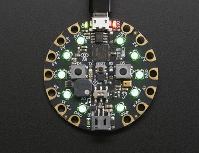
Circuit Playground Express is a board of the Adafruit Wearables line of of e-textile products. This board is beginner friendly since it can (also) be programmed with MakeCode and since it includes both sensor, LEDs and a loudspeaker.
The board is rather large and heavy compared to Adafruit's FLORA and GEMMA. However, this is compensated by it's feature rich design and ease of use.
- 50.6mm / ~2.0"
- Weight: 8.9g
The board can be bought in three packaging variants:
- Circuit Playground Express $25, includes just the board
- Circuit Playground Express - Base Kit, $30, includes a battery and USB cable.
- Circuit Playground Express Advanced Pack, $100, includes 2 Playground express, threads, needles, alligator clips, a servo motor, NeoPixels, etc.
For a class, it's probably best to buy Based Kits, and either a few Advanced Packs or other FLORA extension elements.
Extras
See also:
- Adafruit Wearables (The e-textile line from which other elements like Adafruit NeoPixels, other sensors etc. can be picked and easily connected)
- Adafruit GEMMA (The tiny sister board)
- Adafruit NeoPixel (connecting and programming external Adafruit LEDs)
The board

Components and layouts
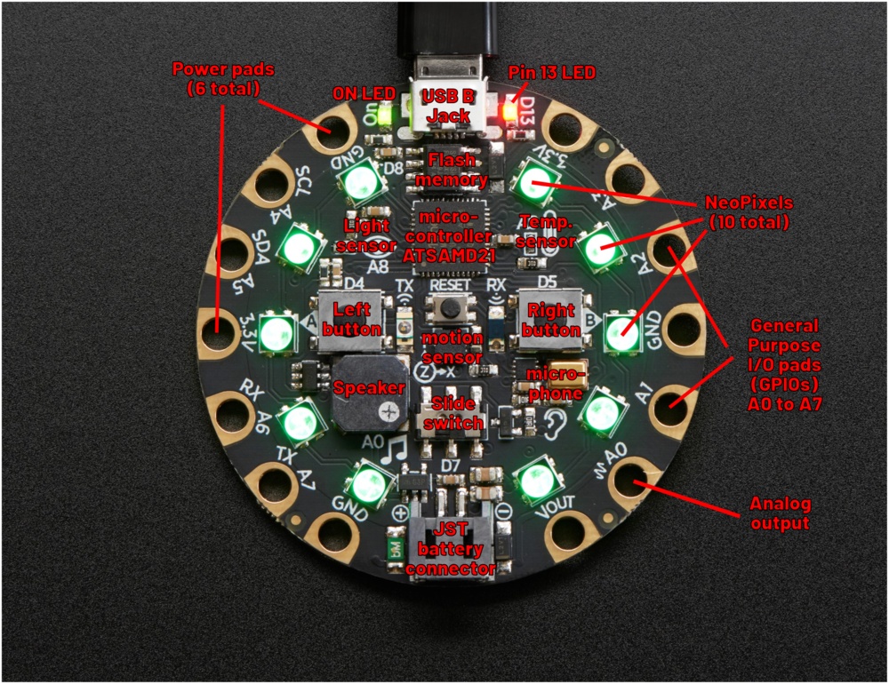
According to the product page (retrieved Aug 26, 2019), this board includes the following elements which are explained in detail in the guided tour.
Processor and basics
- ATSAMD21 ARM Cortex M0 Processor, running at 3.3V and 48MHz
- 2 MB of SPI Flash storage (i.e. a tiny disk drive), used primarily with CircuitPython to store code and libraries.
- A JST battery connector (alternatively, the board also can take power from the USB connector).
- Green "ON" LED so you know its powered (top left)
- Red "#13" LED for basic blinking
- Reset button (in the middle)
- A total of input/output pads ("the holes")
Connectivity:
- MicroUSB port for programming and debugging. It can act like a serial port, keyboard, mouse, joystick or MIDI!
- Infrared receiver and transmitter - can receive and transmit any remote control codes, as well as send messages between Circuit Playground Expresses. Can also act as a proximity sensor.
- 14 "alligator clip pads: a wide range of power pins, I2C, UART, Analog In, Digital In/Out, PWM, and Analog Out.
Output:
- 10 x mini NeoPixels. These programmable LEDs can display any color. They are also used for some status information: when the bootloader is running they will turn green, or if it failed to initialize USB when connected to a computer, they will turn red).
- 1 Mini speaker with class D amplifier (7.5mm magnetic speaker/buzzer). It is connected to to the A0 analog output pin.
Input and sensors:
- 1 Temperature sensor
- 1 Light sensor. Can also act as a color sensor and pulse sensor.
- 1 Sound sensor (MEMS microphone)
- 1 Motion sensor, i.e. a LIS3DH triple-axis accelerometer with tap detection, free-fall detection.
- 2 x Push buttons, labeled A and B
- 1 x Slide switch
- 7 of the 8 GPIO pads have capacitive touch (A1.A2, A3, A4, A5, A6, A7)
General Purpose Input Ouput (GPIO) pads
- All the 8 GPIO pads (A0 to A7) can be used as digital inputs, digital outputs, for LEDs, buttons and switches. In addition, all can be used as analog inputs (12-bit ADC).
Power pads
- There are 6 power pads
Notice: I have to figure out what some of the various pins/pads really do (this is my first electronics experience....)
Programming the board
To computile and upload a program to the controller
- Open
- Connect the board with the USB cable
- Press the reset button (for a while)
- When it turns green, you can download
See also:
Links
Official tutorials
Adafruit Circuit Playground Express documentation
- Adafruit Circuit Playground Express (several pages)
- Adafruit Circuit Playground Express (in one HTML page)
- Adafruit Circuit Playground Express (all-in-one PDF file]
Acknowledgement
Pictures as well as some text was reproduced from the Adafruit circuit playground express documentation. Some pictures are available under a CC BY-NC-SA license. Others are copyright AdaFruit and "all rights reserved" and reproduced with permission. Before you reuse any picture from this website, make sure to look at the license information.
For more information about using Adafruit, see https://learn.adafruit.com