Using Inkscape for web animation: Difference between revisions
| Line 213: | Line 213: | ||
</g> | </g> | ||
...... | |||
--> | |||
<animateTransform id="eye_anim5" | <animateTransform id="eye_anim5" | ||
Revision as of 16:42, 13 February 2014
<pageby nominor="false" comments="false"/>
Introduction
This short tutorial will provide some tips on editing SVG pictures in Inkscape in order to add some SVG-SMIL animation and interactivity with other tools. Inkscape doesn't allow SVG code editing, but it is useful to learn some Inskscape tricks in order to prepare the SVG in order to create animations made from complex clipart that you could find on http://openclipart.org.
Example in this page were tested on Jan 2014 with Firefox and Chrome)
Prerequisites:
- Using SVG with HTML5 tutorial
- Static SVG tutorial
- SVG-SMIL animation tutorial
- Interactive SVG-SMIL animation tutorial (maybe ...)
See also:
Below we will use the following example:
- Dragon head silhouette
- Original: dragon-head-silhouette-by-kuba (openclipart.org)
- Revised version: dragon-head-silhouette.svg
- Animated version: dragon-head-silhouette-anim.svg
Identifying and naming SVG elements
In order to write animation code, it is probably best to give special ID's to the objects that you would like to manipulate.
Procedure:
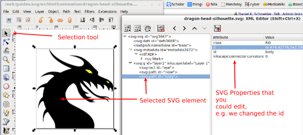
- (1) Open the XML Editor
- Menu: Edit -> XML Editor or (Shift-CTRL-X)
- (2) Use the selection tool to identify objects in the drawing
- Hit F1 (or the top button in the toolbar to the left)
- Select the element, either in the drawing pane or by clicking on elements in the XML Editor
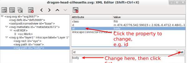
- (3) Click on id in the XML editor
- In the bottom panel, change its name, then click
Set
Path surgery
Simplifying drawings
According to the tutorial advanced, he main use of the Simplify command (Ctrl+L) is reducing the number of nodes on a path while almost preserving its shape. “The amount of simplification (called the threshold) depends on the size of the selection. Therefore, if you select a path along with some larger object, it will be simplified more aggressively than if you select that path alone. Moreover, the Simplify command is accelerated. This means that if you press Ctrl+L several times in quick succession (so that the calls are within 0.5 sec from each other), the threshold is increased on each call. (If you do another Simplify after a pause, the threshold is back to its default value.) By making use of the acceleration, it is easy to apply the exact amount of simplification you need for each case.” (retrieved Jan 2014).
Cutting a path in two parts
Sometimes, e.g. in the dragon head silhouette drawing, the whole SVG picture is just a single path. If you plan to animate some detail, you will have to cut it off.
Procedure:
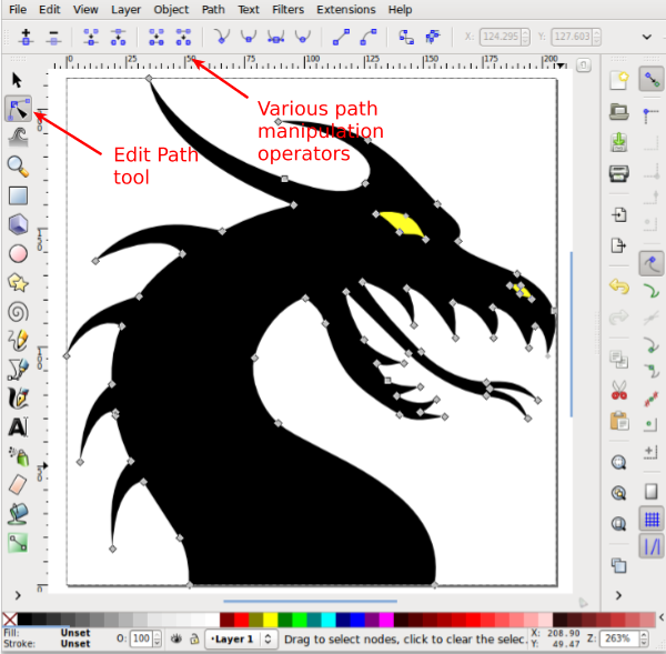
- (1) Get the path edit tool
- Hit F2 or select second tool in the left tool palette
(2) Select the path you plan to edit
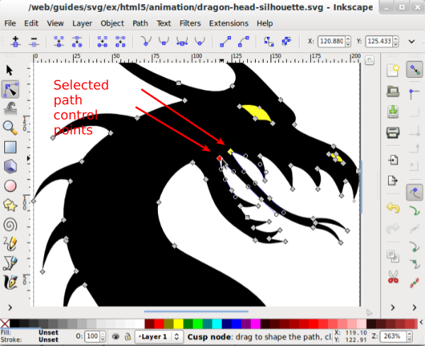
- You now will see control points that you can use to change the shape (but that's not our purpose here)
- Zoom in, e.g.++ by hitting the
+button on the keyboard or by using theViewmenu. Try View->Zoom->Drawing or View->Zoom-Selection
- (3) Cut
- Hold down SHIFT key and select two (not linked) points that will define the cut
- Click
Break path at selected nodesin the upper toolbar - Menu
Path->Break Apartwill break the path into two paths
Some extra tips:
- The breaking may fail, i.e. change the path itself. Undo if this happens.
- If an object is not path (e.g. a rectangle), you can convert it to a path object: (Menu: Path -> Object to Path). But there is no way back !
- Use the XML Editor to select an element if necessary (i.e. if you can't select the one you need)
Constructive solid geometry
Constructive solid geometry is a popular 2D/3D modelin technique that allows to create interesting shapes from other shapes. See the Subtractive geometry in Adobe Flash CS6 where we show how to create a Moon symbol by subtracting a circle from a circle. A similar functionaly exist in Stich Era, Stich Era, an embroidery software. OpenScad is a 3D CAD tool where people design models by coding.
Read:
- Path Operations
- Tutorial advanced (Boolean operations section)
Tips:
- In order to achieve what you want you often will have to destroy objects. In other words, you may first have to create copies. Either move these away temporarily or just pile 2 objects on top of each other: CTRL-C, deselect, then CTRL-SHIFT-V
Example to create an eye from a dragon head outline
- Draw a yellow rectangle over the eye
- Move it backwards: Menu: Object -> Lower (or PageDown key) and position. You now should see a yellow eye
- Copy / Paste in place the dragon head. In the XML Editor, you now should see a new path
- Select both dragon head and a rectangle
- Menu: Path -> Difference or
CTRL- - You know should have an eye.
Adding animation in Inkscape
You cannot ! Therefore, we suggest to export the drawing to simple SVG and to use a text editor.
If you added objects to animated and if you did change the id's names as suggested above, programming will now be much easier. Make sure to add xmlns:xlink="http://www.w3.org/1999/xlink" declaration in the SVG root if you use any sort of links !!
Dragon example
- http://tecfa.unige.ch/guides/svg/ex/html5/animation/dragon-head-silhouette-anim.svg
- http://tecfa.unige.ch/guides/svg/ex/html5/animation/dragon-head-silhouette-anim.html (HTML5 version that includes the SVG with an object element)
The animation code we added at the end of the file (using linking) is:
    <animate xlink:href="#eye"
	     dur="12s" begin="1s"
	     to="#000000" from="#CC9933"
	     repeatCount="indefinite"
	     calcMode="linear" attributeName="fill"/>

    <animate id="nose_anim1"
	     xlink:href="#nose"
	     dur="2s" begin="0s; nose_anim2.end"
	     from="yellow" to="red"
	     attributeType="CSS"
	     calcMode="linear" attributeName="fill"/>

    <animate id="nose_anim2"
	     xlink:href="#nose"
	     dur="2s" begin="nose_anim1.end"
	     to="yellow" from="red"
	     calcMode="linear" attributeName="fill"/>

    <animate id="tongue_anim1"
	     xlink:href="#tongue"
	     dur="6s" begin="1s; tongue_anim2.end"
	     to="#501616" from="black"
	     calcMode="linear" attributeName="fill"/>

    <animate id="tongue_anim2"
	     xlink:href="#tongue"
	     dur="6s" begin="tongue_anim1.end"
	     from="#501616" to="black"
	     calcMode="linear" attributeName="fill"/>

    <animateTransform id="tongue_anim1a"
	     xlink:href="#tongue"
	     dur="6s" begin="1s; tongue_anim2a.end"
	     to="0.99" from="1.0"
	     attributeName="transform" type="scale"
	     />
    <animateTransform id="tongue_anim2a"
	     xlink:href="#tongue"
	     dur="6s" begin="tongue_anim1a.end"
	     from="0.99" to="1.0"
	     attributeName="transform" type="scale"
	     />
Notice:
- Rotations in the HTML file were made with CSS, i.e. we rotate the HTML object element.
- The header of the SVG file (includes a viewBox and set width and height to 100% (good for inclusion in HTML5)
- the chaining of the nose and tongue animation as explained in the SVG-SMIL animation tutorial
- Doing transform animations can be very hairy with imported pictures, because drawings are often transformed in various ways and animating these has strange effects on the coordinate system. The same is true for motion animation. E.g. instead of redrawing a tongue, we just cut it off an existing path. Scaling will scale the whole coordinate system used to define the tongue, not just the tongue itself ...
Dealing with path objects
Animating the size of a path element or doing a motion animation with a path element can be very hairy, since this type of animation actually changes the coordinate system of the element. For example, when you grow a path using a animateTransform, the element may just move somewhere. If you understand math, you probably could figure out a good solution. I can't, therefore I suggest the following strategy:
- From your animated SVG file, copy / paste the path you plan to animate to a new SVG file
- Adjust the drawing Canvevas: Menu: File->Document Properties->Custom Size; Select Resize page to drawing or selection
- Save the new file as optimized SVG
- Insert an svg element into the animation file
- Copy/paste the code from the new SVG file between the
svgelement - Adjust the the x and y position of the <svg>element
Example:
- http://tecfa.unige.ch/guides/svg/ex/html5/animation/paulliu_girl_with_silver_hair.svg (Copy of the original (from openclipart.org)
- http://tecfa.unige.ch/guides/svg/ex/html5/animation/paulliu_girl_with_silver_hair-mod2.svg (Includes a simple size animation)
- http://tecfa.unige.ch/guides/svg/ex/html5/animation/girl_eye_left.svg (just an eye)
Code excerpt:
  <desc>-------------------------------------------------------------------------</desc>
  <desc>Below is some substituted code for the eye. We use a embedded svg element</desc>

  <svg viewBox="0 0 28.5 33.2"
       width="28.5" height="33.2"
       x="369" y="143"
       >
    <defs id="defs6005">
      <linearGradient id="eyeGrad" y2="193.43" gradientUnits="userSpaceOnUse" y1="159.23" gradientTransform="matrix(0.95876002,-0.28420001,0.28420001,0.95876002,-353.16135,-55.73074)" x2="315.38" x1="314.7">
	<stop stop-color="#000000" offset="0"/>
	<stop stop-color="#b9b9b9" offset="1"/>
      </linearGradient>
      <linearGradient id="eyeGrad2" y2="193.43" gradientUnits="userSpaceOnUse" y1="159.23" gradientTransform="matrix(0.95876002,-0.28420001,0.28420001,0.95876002,-353.16135,-55.73074)" x2="315.38" x1="314.7">
	<stop stop-color="#000000" offset="0"/>
	<stop stop-color="#00ffff" offset="1"/>
      </linearGradient>

    </defs>
    <g id="eye_left" transform="translate(14.286238,-7.203961)">
      <path id="path4885" stroke-linejoin="round" d="m12.943,19.954a16.25,13.5,73.489,0,1,-25.887,7.6734,16.25,13.5,73.489,0,1,25.887,-7.6734z" stroke="#000000" stroke-linecap="square" stroke-width="1.09999478" fill="url(#eyeGrad2)"/>
    </g>
    <circle id="pupil_left" r="1" cx="15" cy="15" fill="#8b0000"/>
  </svg>

  <!-- original eye removed
  <g
     id="eye_left">
    <path
       d="m 329.5,176.61218 a 13.5,16.25 0 1 1 -27,0 13.5,16.25 0 1 1 27,0 z"
       transform="matrix(0.95876,-0.2842,0.2842,0.95876,28.837,77.84)"
       id="path4885"
       style="fill:url(#linearGradient6649);stroke:#000000;stroke-width:1.10000002;stroke-linecap:square;stroke-linejoin:round" />
  </g>

  ......
  -->

  <animateTransform id="eye_anim5"
	     xlink:href="#eye_left"
	     dur="6s" begin="1s"
	     values = "1.0;0.9;1.0"
	     repeatCount="indefinite"
	     additive="sum"
	     attributeName="transform" type="scale"/>

  <animate id="eye_anim6"
	     xlink:href="#pupil_left"
	     dur="6s" begin="1s"
	     values = "1;2;1"
	     repeatCount="indefinite"
	     attributeName="r"/>
Optimizing and translating to plain SVG
Since Inkscape is primairly a drawing tool and not a web drawing tool, it includes extensions that add functionality to the editor (e.g. layers) and power to "plain" SVG. According to the XML standard this is perfectly legal if a namespace mechanism is used. Web browser do not understand the "inkscape" and "sodipodi" elements and simply ignore these.
In addition, drawings may use weird coordinates, include unused definitions, the drawing canvas may be too big, etc. In other words you also should optimize the drawing. This particularly important if you plan to import SVG drawings to HTML5 via the object or the img element.
Therefore, in order to insure that pictures show as intended, you should try both optimizing and translating to plain SVG. This will not always work.
If possible, do the following (as also explained in the Using SVG with HTML5 tutorial:
- Optimizing
- Fit the document size to the picture size: Menu File->Document Properties. In the Custom size panel, open Resize page to content, then click Resize page to drawing or selection.
- Remove unused DEF's: File->Vacuum Defs.
- Optimize SVG: File -> Save as... -> Optimized SVG.
- Tick "Enable viewboxing in the save dialog. This operation will do two things, Insert correct viewBox, and set width and height attributes to 100% (this is very useful if you plan to import drawings with the HTML object or img tags, i.e. you can easily define the SVG image size).
- You may untick "Simply colors"
- Translate to plain SVG
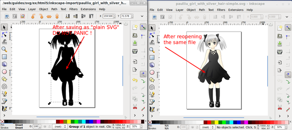
- Remove non-standard SVG/Inkscape XML: File -> Save as... -> plain SVG (Since this operation will remove layers and other Inkscape specific information, keep a copy of the old file if necessary)
- As of Jan 2014, this operation may seem fail, e.g. the whole picture becomes black for a reason we can't figure out. Save the file under a different name, then re-open it again. The blackness may just be a display error. Do not panic !
Links
Official
- Tutorials
- Tutorial advanced shows tips and tricks to edit and to simplify drawings
Tutorials
- Inkscape: Guide to a Vector Drawing Program by Tavmjong Bah. This is a free online version of the Inkscape: Guide to a Vector Drawing Program, 4th Edition Print Book or Ebook
- Different versions are available at: http://tavmjong.free.fr/INKSCAPE/
- For example, have a look at Chapter 23. SVG and the Web
