LilyPad ProtoSnap Plus
Introduction

The LilyPad ProtoSnap Plus is a sewable electronics (e-textile) prototyping board that you can use to explore circuits and programming, then break apart to make an interactive fabric or wearable project.
The LilyPad ProtoSnap Plus can be bought alone or in a kit that includes wires, USB B cable, needles and a battery.
The board
Overview
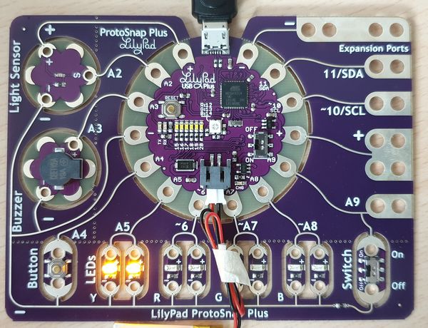
“At the center of the ProtoSnap Plus is a LilyPad USB Plus microcontroller, pre-wired to LilyPad pieces including a LilyPad Light Sensor, LilyPad Buzzer, LilyPad Button Board, four pairs of colored LilyPad LEDs, and a LilyPad Slide Switch. Because these components are connected together on the ProtoSnap board, you can test out your project ideas before you sew. The ProtoSnap Plus also includes Expansion Ports; these let you use alligator cables to easily connect external sensors and components to the board. After testing out your coding ideas using the attached LilyPad pieces, you can break apart the board and sew them into your project.” (LilyPad ProtoSnap Plus Hookup Guide, retrieved Aug 27, 2019).
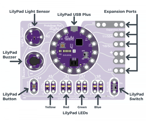
The LilyPad USB Plus
“The LilyPad USB Plus is an Arduino-compatible microcontroller similar to the LilyPad Arduino USB - ATmega32U4 Board but with some additional features and three additional sew tabs. It is currently only available on the LilyPad ProtoSnap Plus.” (LilyPad ProtoSnap Plus Hookup Guide, retrieved Aug 27, 2019)
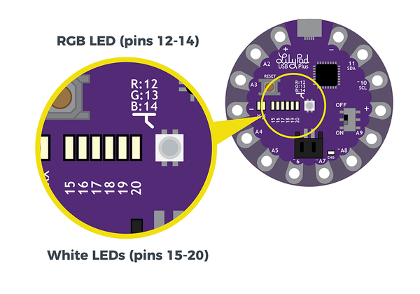
This micro-controller includes the following:
- USB B port for connecting to a computer.
- Two sets of power (+) and ground (-) sew tabs.
- Built-in RGB LED attached to pins 12 (R), 13 (G), and 14 (B).
- A row of six small white LEDs attached to pins 15-20.
- Charging circuit for single-cell (3.7V) Lithium-Polymer batteries.
The different sew tabs and their wired connections to the snap-off components are documented in detail in a table of the LilyPad ProtoSnap Plus Hookup Guide (retrieved Aug 2019) that we produced below in slightly modified form
| LilyPad Component | Connected to LilyPad USB Plus Sew Tab | Description |
|---|---|---|
| LilyPad Light Sensor (S) | A2 | LilyPad USB Plus receives ambient light level input from light sensor. |
| LilyPad Buzzer (+) | A3 | A buzzer that create tones, controlled by LilyPad USB Plus. |
| LilyPad Button | A4 | LilyPad USB Plus receives button press input. |
| 2x LilyPad Y LEDs (+) | A5 | A pair of yellow LEDs controlled by LilyPad USB Plus. |
| 2x LilyPad R LEDs (+) | ~6 | A pair of red LEDs controlled by LilyPad USB Plus. |
| 2x LilyPad G LEDs (+) | ~A7 | A pair of green LEDs controlled by LilyPad USB Plus. |
| 2x LilyPad B LEDs (+) | ~A8 | A pair of blue LEDs controlled by LilyPad USB Plus. |
| LilyPad Switch | A9 | LilyPad USB Plus receives switch state (on/off) input to change modes. |
| Expansion Port A9 | A9 | Clippable pads to connect another LilyPad piece to. Shares connection with the LilyPad Switch. |
| Expansion Port (+) | (+) | Clippable pads connected to LilyPad USB Plus's power (+) sew tab. |
| Expansion Port ~10/SCL | ~10/SCL | Clippable pads connected to LilyPad USB Plus's sew tab 10. This can be used to connect to a I2C clock pin. |
| Expansion Port 11/SDA | 11/SDA | Clippable pads connected to LilyPad USB Plus's sew tab 11. This can be used to connect to a I2C data pin. |
| Expansion Port (-) | (-) | Clippable pads connected to LilyPad USB Plus's ground (-) sew tab. |
| All components (-) | (-) | All components share a common ground connection back to the LilyPad USB Plus. |
Powering / Charging
The LilyPad USB Plus board can draw from the USB B cable and will recharge the little lithium battery. Read the details
Programming the LilyPad USB Plus
You must either install the Arduino IDE, version 1.8.9 or use the Arduino online editor, but we did not figure out how to add this board to the latter (or if it is possible in the free version)
Installing the Arduino IDE software on your desktop computer
For Windows 10:
- Download the Arduino software: https://www.arduino.cc/en/Main/Software
- Install it.
- Windows 7 may need some extra work to install the drivers (read the above manual)
Configure the Editor
You will have to to configure your board in the editor.
Step 1 - Add Sparkfun URL
- In Menu File -> Preferences add the following URL at the bottom of the page.
https://raw.githubusercontent.com/sparkfun/Arduino_Boards/master/IDE_Board_Manager/package_sparkfun_index.json
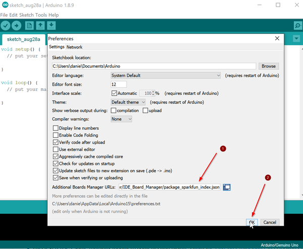
Step 2 - Add board information
(read the official text if the following is too short for you):
- In Menu Tools -> Board -> Board Manager, select Boards manager..
- In the Boards manager windows that will open, search for "Sparkfun"
- Select SparkFun AVR Boards by SparkFun Electronics
- Click on Install, selecting the latest version
- If successful, the word "INSTALL" should appear next to it.
Step 3 - Connect the board and select both board and the USB port
- (re)connect the Board. Switch it off before disconnecting and on after connecting (I guess that is healthier)
- Select Tools -> Board, then at the bottom of the menu select LilyPad USB Plus
- Select Tools -> Port, then select "... LilyPad USB Plus". On my system it was on COM5.
These three steps have to be performed each time
Programming the LilyPad USB Plus
Before you start exploring this, make sure that you correctly configured the Arduino IDE as described above, e.g., the LilyPad USB Plus appears in the File -> Board and Port menus.
You now can use the example code that is provided in this location:
- Menu File -> Examples -> LilyPadProtoSnapPlus
Blinking LED
This code is fairly simple and includes two parts
- The
setup()function will be called first and is used to initialize things. In our case we set the A5 pin for output. - The following loop will make the LED blink.
The code below is documented, read it.
Step 1
Open Menu File > Examples > LilyPadProtoSnapPlus > LPP_01_Blink
/*
LilyPad ProtoSnap Plus Activity 1: Blinking LEDs
SparkFun Electronics
https://www.sparkfun.com/products/14346

Blink the pair of yellow LEDs attached to sew tab A5 on the LilyPad USB Plus

Follow the tutorial at:
https://learn.sparkfun.com/tutorials/lilypad-protosnap-plus-activity-guide#1-blinking-leds

This example is based on: Blink by Scott Fitzgerald
https://www.arduino.cc/en/Tutorial/Blink

This code is released under the MIT License (http://opensource.org/licenses/MIT)

******************************************************************************/

// The setup function runs once when the microcontroller starts up or resets:

void setup()
{
  // Before you use a sew tab (pin), you must set it to be either an input or output:

  pinMode(A5, OUTPUT);    // Set pin A5 to be an output
}

// After the setup function runs, the loop function runs over and over forever:

void loop()
{
  digitalWrite(A5, HIGH); // Give pin A5 a HIGH voltage level (on), which lights up the LED
  delay(1000);            // Pause for 1000 milliseconds (one second), the LED stays on
  digitalWrite(A5, LOW);  // Give pin A5 a LOW voltage level (off), which turns off the LED
  delay(1000);            // Pause for 1000 milliseconds (one second), the LED stays off
}
Step 2
Compile and upload to the board
- Click on the the button with the -> arrow.
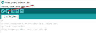
The yellow LED hooked to A5 now should blink.
Buttons and Switches
The following example shows how to use a button and a switch. Again, we just copied it from the tutorial and we only made small modifications in the comments.
/*
LilyPad ProtoSnap Plus Activity 6: Buttons and Switches
SparkFun Electronics
https://www.sparkfun.com/products/14346

Explore digital input and program flow control using the button and switch

Follow the tutorial at: https://learn.sparkfun.com/tutorials/lilypad-protosnap-plus-activity-guide#6-buttons-and-switches

This code is released under the MIT License (http://opensource.org/licenses/MIT)

******************************************************************************/

// Create integer variables for the pins we'll be using

int buttonPin = A4; // the button component is connected to A4
int switchPin = A9; // the switch is connected to A9

int buttonLED = A5; // yellow LEDs
int switchLED = A8; // blue LEDs

void setup()
{
  // Initialize the button and switch pins as inputs with pullups.
  // Pullups keep the inputs from "floating" when a switch or button is open / unpressed.

  pinMode(buttonPin, INPUT_PULLUP);
  pinMode(switchPin, INPUT_PULLUP);

  // Initialize the LED pins as outputs:

  pinMode(buttonLED, OUTPUT);
  pinMode(switchLED, OUTPUT);
}

void loop()
{
  // This code will read the positions of the button and switch,
  // then use the "if" command to make LEDs follow these states.

  // Create variables to store the button and switch input values:

  int buttonState;
  int switchState;

  // Read and save the states of the button and switch:

  buttonState = digitalRead(buttonPin);
  switchState = digitalRead(switchPin);

  // The if-else statement lets you do different things based on different inputs:

  // The button will read as LOW when it's pressed

  if (buttonState == LOW) // Check to see if buttonState is LOW (pressed)
  {
    digitalWrite(buttonLED,HIGH); // If buttonState is LOW (pressed), turn on the yellow LED
  }
  else
  {
    digitalWrite(buttonLED,LOW); // If buttonState is HIGH (unpressed), turn off the yellow LED
  }

  if (switchState == LOW) // Check to see if switchState is LOW (switch is on)
  {
    digitalWrite(switchLED,HIGH); // If switchState is LOW (on), turn on the blue LED
  }
  else
  {
    digitalWrite(switchLED,LOW); // If switchState is HIGH (off), turn off the blue LED
  }
}
Links
- LilyPad ProtoSnap Plus Hookup Guide (A detailed description of the board and how to use it, e.g. installation of the development environmment)
- LilyPad ProtoSnap Plus Activity Guide
Acknowledgment and Copyright modification
- This text reuses some (partially modified) contents and pictures from the LilyPad ProtoSnap Plus Hookup Guide and the LilyPad ProtoSnap Plus Activity Guide.
- Therefore, contents of this page (including pictures) are also available under a CC BY-SA 4.0 license. In short, you can copy and redistribute the material in any medium or format, remix, transform, and build upon the material for any purpose, even commercially. under the following conditions: You must give appropriate credit, provide a link to the license, and indicate if changes were made. If you remix, transform, or build upon the material, you must distribute your contributions under the same license as the original.