UML class diagram
Definition
UML Class diagrams are one kind of official diagram types of the Unified modeling language (UML). They describe the structure of a system.
“If someone were to come up to you in a dark alley and sy, "Psst, wanna see a UML diagram?" that diagram would probably be a class diagram.”(Fowler, 1993:35).
“A class diagram describes the types of objects in the system and the various kinds of static relationships taht exist amoung them. Class diagrams also show the properties and oprations of a class and the constraints that apply to the way objects are connected. The UML uses the term feature as a general term that covers properties and oprations of a class.” (Fowler, 1993:35).
Architecture
Class diagrams are made with quite a complex "language". Here are some elements (I know I have to go over this - Daniel K. Schneider 16:45, 5 June 2007 (MEST))
- Classes
- Classes are represented with boxes
- Represented by: a rectangle with one, two or three "fields": classname, properties (attributes) and operations.
- Properties are structural elements of class. Now it get's a little bit complicated. You can describe a property either with an attribute (i.e. within the class box) or with an association (see below).
- Association
- A relationship between two classes or properties
- Represented by: a solid line, or if directional with an arrow directed from the source object to the target object, or if bidirectional with an arrow on both ends.
- Aggregation
- A part-of relationship
- Represented by: a solid line, with an emtpy lozange at aggregation end and arror at member end
- Example: a learning object is part of an environment
- Generalization
- A is-a relationship
- Represented by: A solid line with a triangular arrow from specialized class to class
- Example: Learner is a role
- Composition
- Like aggregation but you can add more constraints.
- An instance of a class can be potentially a component of several classes, but can only be owned by one.
- Represented by: a solid line, with an filled lozange at aggregation end and arror at member end
- Multiplicity
- of an association end is the number of possible instances of the class associated with a single instance of the other end.
- Represented on both ends by the following syntax
| Multiplicities | Explanation The notation n . . m indicates n to m instances. |
|---|---|
| 0..1 | zero or one instance. |
| 0..* or * | no limit on the number of instances (including none). |
| 1 | exactly one instance |
| 1..* | at least one instance |
- More
- There is more (sorry)...
Examples
IMS Learning Design
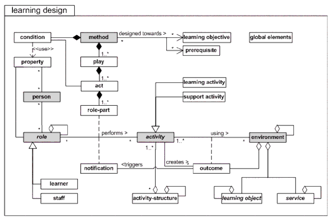
Here is the official UML Diagram that summarizes the IMS Learning Design educational modeling language:
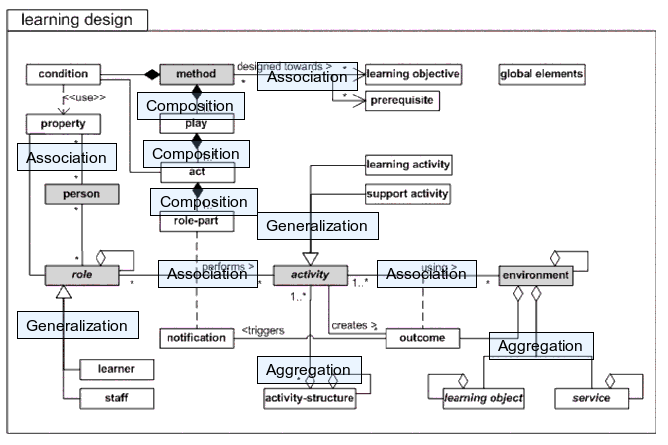
Here is an annotated version. Blue boxes (roughly) give an idea of the relationships involved.
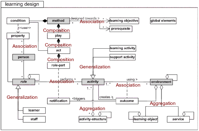
Here is second try. Annotation is in red (blue boxes wouldn't show well enough when I pasted this into a word processor)
References
On line tutorials
- IMS Learning Design Information Model, Version 1.0 Final Specification, HTML, retrieved 16:45, 5 June 2007 (MEST).
- Randy Miller, Practical UML: A Hands-On Introduction for Developers, Borland Developer network. (Short and excellent general UML tutorial).
- Donald Bell, UML basics: An introduction to the Unified Modeling Language, IBM Developper Works / Rational Rose. (IBM has a lot of UML and use case tutorials, needs some searching skills)
Books
- Fowler Martin (1993). UML Distilled: A Brief Guide to the Standard Object Modeling Language, Third Edition. Addison-Wesley Professional. ISBN 0321193687 (good for quick reference and good enough if you just want to understand how to read UML diagrams).
- Pilone, Dan and Neil Pitman (2005). UML 2.0 in a Nutshell, O'Reilly Media, ISBN 0596007957 (this is the best book Daniel K. Schneider bought, better than the first edition).


