Flash inverse kinematics tutorial
This article or section is currently under construction
In principle, someone is working on it and there should be a better version in a not so distant future.
If you want to modify this page, please discuss it with the person working on it (see the "history")
<pageby nominor="false" comments="false"/>
This is part of the Flash tutorials
Introduction
- Learning goals
- Insert bones in shapes
- Connect symbols with bones
- Create a motion animation with bones
- Attach envelope points to bones
- Flash level
- Flash CS4 - Flash 10 (!)
- Some examples work with the Flash 9 player
- Prerequisites
- Basic drawing and animation (e.g. the level of Flash animation summary)
- Moving on
- See the Flash tutorials
- Level and target population
- Beginners
- Quality
- low (just started)
The bones tool is an inverse kinematics (IK) tool with which one can create armatures for shapes or connected symbols instances. These armatures connect objects or parts of shape in a hierarchical tree. These parts can be called bones or limbs. "Outer" (or child) limbs that are moved also will move "inner" (or parent) limbs. E.g. In a human avatar, if you pull a finger, the hand will move too and the hand in turn will move the lower arm, etc. So in contrast fo "forward kinematic animation", where each movement for each component must be planned, only the starting and ending locations of a limb are necessary to get a basic animation going.
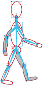
“Inverse kinematics is the process of determining the parameters of a jointed flexible object (a kinematic chain) in order to achieve a desired pose. Inverse kinematics is a type of motion planning. Inverse kinematics are also relevant to game programming and 3D animation, where a common use is making sure game characters connect physically to the world, such as feet landing firmly on top of terrain.” (Wikipedia, retrieved 27 November 2008 ).
“Inverse kinematic animation (IKA) refers to a process utilized in 3D computer graphic animation, to calculate the required articulation of a series of limbs or joints, such that the end of the limb ends up in a particular location. In contrast to forward kinematic animation, where each movement for each component must be planned, only the starting and ending locations of the limb are necessary.” (Inverse kinematic animation, retrieved 17:52, 28 November 2008 (UTC)).
“The characters in a game have skeletons. Similar to our own skeleton, this is a hidden series of objects that connect with and move in relation to each other. Using a technique called parenting, a target object (the child) is assigned to another object (the parent). Every time the parent object moves, the child object will follow according to the attributes assigned to it. A complete hierarchy can be created with objects that have children and parents [...] Once the skeleton is created and all of the parenting controls put in place, the character is animated. Probably the most popular method of character animation relies on inverse kinematics. This technique moves the child object to where the animator wants it, causing the parent object and all other attached objects to follow.” (How stuff works, retrieved 27 November 2008).
Adobe CS4 fully integrates inverse kinematics modelling with their drawing tools. “Inverse kinematics (IK) is a method for animating an object or set of objects in relation to each other using an articulated structure of bones. Bones allow symbol instances and shape objects to move in complex and naturalistic ways with a minimum of design effort. For example, inverse kinematics lets you create character animation, such as arms, legs, and facial expressions much more easily.
You can add bones to separate symbol instances or to the interior of a single shape. When one bone moves, the other connected bones move in relation to the bone that initiated the movement. When animating using inverse kinematics you need only specify the start and end positions of objects. Inverse kinematics lets you create natural motion much more easily.” (Using inverse kinematics, retrieved 27 November 2008).
- Simple demo
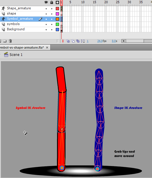
The following application shows the difference between an IK structure (armatrue) made with red symbols and an another made with a blue shape.
Load the symbol-vs-shape-armature.html application and drag the tips (or other parts of the shapes around. Make sure that you have a Flash 10 player installed. Else, it will not work. Notice: The armatures have been defined as type "Runtime", meaning that we let the user do the animation (manipulate the IK structure).
Source:
A simple armature with symbol instances
Creation of a simple IK animation with symbol instances
Have a look at the symbols-ik-armature-intro example first.
- A connected balls and ovals example
- Step 1 - create the symbols
- Create a new layer
- Create a movie clip symbol, draw a red ball and right-click convert to symbol. Select "Movie clip".
- Then adjust the instance on stage (e.g. fix its color and size or add a bevel filter)
- Then create copies of this instance. The fastest way is to hold down CTRL-ALT and drag.
- Repeat this with a rounded rectangle.
In your library you now should have two Movie clip symbols, e.g. Red ball and Red rectangle
- Step 2 - move the symbols into an initial position
- E.g. try to reproduce the example. Make sure that you have all the symbols you need on the stage. You won't be able to add additional symbols once you start defining the armature.
- Step 3 - create the chain
The chain should be going from parent to children, from children to great children etc. In our case, this means that we start with the rectangle that is attached to the floor.
- Select the bone tool and click on the first shape to designate it as the parent shape. The spot where you click first will be the one that attaches the armature to the scene. I our case we selected it close to the floor.
- Then, from from the end point of first point, i.e. the joint', drag the bone tool to the next shape and release the mouse where you want your bone to end. If you release the mouse outside of a symbol (shape) nothing will happen.
- Repeat this step until all of the symbols are linked. Always start from a joint. In our case, always the "outer" joint, since we want to create a chain.
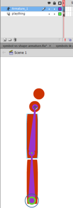
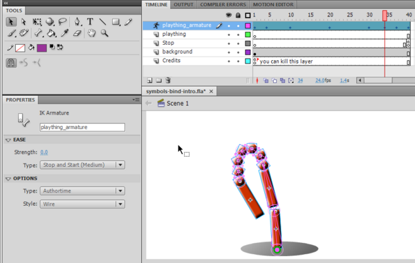
You now will see that Flash now created an armature layer (called "Armature_1" and you can't edit your objects anymore. They have been copied to the armature layer and did become ikNodes. You may change the name of that layer if you like.
A note on terminology: Each bone will get a name like "ikBoneName1" (that you can change) and each connected symbol will get a name like "ikNode1" (that you also can change). So in a IK armature we got bones and nodes.
Now you can play a bit, e.g. drag the last child in the IK structure around and see if the joints are in the right place. If not, adjust (see below)
Adjustments
- Adjust center points
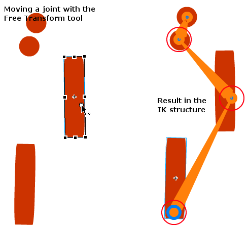
- If the start of a bone is in the wrong place, you can move the rotation point with the free transform tool. You also could turn the shape, move it or adjust its size, so that it would adjust to the new rotation and length of the bone, but that's a bit tricky. You will learn move about bone and node manipulation later, but for starters this it is enough to move bones up and down.
The picture below shows what happens if you move a shape and change its rotation point. The result is not entirely convincing ...
Animation
Let's now create an IK animation. Before you start, make sure that the IK structure is what you want. It must be complete. You won't be able to change the stucture itself later on. You only can change poses, do some transformations and other more advanced tuning. So here is the procedure.
- Hit F5 somewhere in the timeline
- Use the select tool
- Move all the joints wherever you want in any frame you like. Each time you do this, it will create a new keyframe with a pose. Keyframes are represented by little lozenges.
- You can copy/paste poses: Right-click directly in the timeline on a keyframe (i.e. an existing pose) and copy pose. Then right-click in a different frame and paste pose. Make sure to directly right-click (no click first), else it won't work.
What if you got it all wrong ?
- Select the armature layer by clicking on it. This selects the whole IK structure
- Kill the parent bone (in our example it its on the bottom)
- The select all symbols and copy them back to the initial layer ("plaything" in our case). You could use ctrl-shift-v to "copy in place".
- Then delete the armature layer and start again.
Adjustment of the time line
- Just drag the latest frame out or in. Make sure that you see a horizontal double arrow, i.e. don't click in the last frame. In the latter case you would just move the whole animation chain to the right.
- Result and source
- symbols-ik-armature-intro.html
- Source: symbols-ik-armature-intro.fla (Notice: Selection of elements behaves strangely, maybe because I changed features of the symbols or because of the bevel. Simply magnify to 400% if you want to play with it ...).
- Directory: http://tecfa.unige.ch/guides/flash/ex4/inverse-kinematics/
Adding armatures to shapes
You also can add an armature to a shape as we have seen in the inital demo shown at the start. I recommend the following steps:
- Step 1 - Create a new layer with a single shape
- Draw a shape or a simple drawing in object mode. Make sure to finish the drawing, later you only can adjust its shape.
- Make that you only have a single shape, else CS4 will sort of freak out, e.g. freeze a bit or create more than one armature layers ....
I suggest the following procedure for drawing:
- Draw all the parts of the shape in object mode
- Once you are happy, you should save a copy of your artwork in case you want to come back to it later: CTRL-A and Right-click; Create Symbol.
- Then break a part the symbol instance on the stage and make a union' of all graphics: CTRL-A, then menu Modify->Combine Objects->Union. This is necessary because you do need a single shape or drawing object.
- Add the inverse kinematic structure (bones)
- Select the bone tool from the tool panel
- Click inside the shape where you the the armature to be attached to the scene. The parent point will not move.
- Then hold down the mouse at the same spot and drag out a bone
- Click at the end point of this new bone and drag again
- etc.
You now will see an armature layer and you can't edit your objects anymore since they all have been moved to the armature layer.
- Add another shape.
- If you want to create an other IK structure (shape or symbol-based) just create a new layer and start again.
- Adjust
- See previous explanations and tools and objects overview.
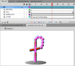
- Two flowers example
This example is really ugly. I would have to do it again. It seems that using the pencil tool (strokes), for the blue flower was not such a good idea. If you need fat lines, rather use the rectangle tool or the paint tool. Then you could adjust the envolope later on.
- bones-in-shape-intro.html
- Source: bones-in-shape-intro.fla
- Directory: http://tecfa.unige.ch/guides/flash/ex4/inverse-kinematics/
- Shape stickman example
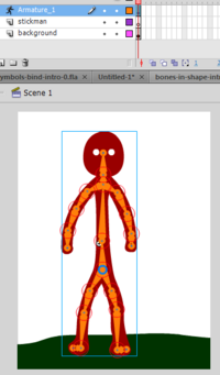
This shape has been drawn with the Paint tool in object mode. Once the drawing was done, we made a union of all its parts (Modify->Combine Objects->Union) and then optimized (Modify->Shape-Optimize) at 100%.
- The stickman has many joints as you can see in the picture.
- The parent bone starts in the hip area.
- We not only animated the poses but also move the stickman in different positions in various keyframes.
- shape-ik-stickman-animation.html
- Source: shape-ik-stickman-animation.fla
- Directory: http://tecfa.unige.ch/guides/flash/ex4/inverse-kinematics/
The result isn't great, but given the time we spent on it (little) it's ok.
- Fixing the shape in poses
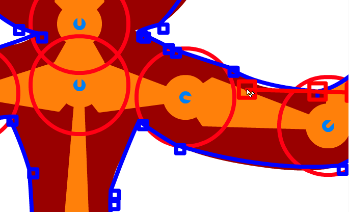
You sometimes can see that the shape doesn't really follow the bones (I mean these sharp edges that can appear). Such behavior can be fixed:
- Use the subselect tool to move shape control to a different place. Firstly, magnify the scene (at least 400%). Then you can move or kill the blue control points or adjust them with the red curve control handlers. Take it slowly and wait to see the result of a manipulation! Even my DELL M1740 high-end laptop needs to think about it, before it let's me see a deletion, a move or a curve change happen. Also bones may be shown displaced. Click in another keyframe and come back ...
- Use the bind tool to associate shape controls with bones.
Unless you are looking for a "snake-like" behavior, it is probably better to use a symbol-based armature as in the next chapter.
A stickman avatar
Let's now create a stickman avatar that roughly has human proportions. In order to create a "human" stick man we need a few objects to represent body parts. Here are a few rules of thumbs regarding size of body parts:
- Total body height should be about 6-8 times the size of the head
- Head to crotch and crotch to feet is about the same size
- shoulders and hips are about the same (shoulder is smaller for females and bigger for males)
- Waist (if you have one is midway between shoulders and crotch
- Arm length: From shoulder to mid-thigh (or shorter)
- Feet length: About the same as forearm
- Face is an oval, about 6-8 smaller than the total size. Eyes are roughly in the middle.
- Adjust properties
Select a bone and play with the options in the properties panel
- Speed refers to the rotation speed in relation to the rest (default is 100%)
- Joint rotation constraints are rotational constraints on the joints of an artificial bone system
Animation by user action
You can produce a inverse kinematics armature that the user can manipulate. To do so:
- Only use frame 1 of the Armature layer, i.e. don't do any animation (kill all the other frames in the Armature layer)
- In the properites panel, choose Type -> Runtime.
- You now can play the movie (publish it) and play.
Tools and objects overview
This is a sort of short manual for the IK tools an objects
Tools
Below is a list of tools you may use and their function. See further down for "how to".
- The Bones tool
- Define bones
- The Bind tool
- Associate envelope points with a given bone. (more later)
- The Select tool
- Select bones or associated ikNodes (shapes) for further manipulation, either by dragging, ALT-dragging or via the properties or transform panel.
- The Subselection tool
- Allows you to move joints of bones (i.e. make them longer or shorter and rotate) of bones within a shape armature. I.e. this won't work with IK structures that use symbols. To move bones for symbol armatures, use the FreeTransform tool.
- Allows to ajust shapes
- The pen tool
- As alternative tool to add/remove control points to a shape.
- The Freetransform tool
- Allows to move joints (starting points of bones) of an symbol-based armature.
- The Transform panel
- Change size and rotation of both bones and associated ikNodes (shapes).
Manipulating bones and shapes
- The armature layer
An armature is defined in a special Armature layer. By clicking on the layer, you then can change some of its properties in the properties panel:
- Ease: You can define ease-in and ease-out paramters as in other tweening animations
- Options:
- Change type: Authortime to animate yourself in the armature layer, runtime to allow the user move the IK structure. In the latter case, you can't have your own animations. I.e. you only can define frame 1.
- Style: This will display the bone structure in various ways. Use solid for simple stuff and wire to be able to work on finer details.
Flash automatically moves all the object from the drawing layer to the armature layer as soon as you create an IK. Therefore if you want to break the armature, make sure to copy first all your stuff from the armature layer to another layer or much better, before you start adding an armature, simply save your drawings as a symbol in the library (break apart the instance on stage again after you saved).
Also, armatures can only be edited after you created it, i.e. you may edit the structure of the initial pose. If you have more than one pose, i.e. more than one frame, you can't. In the other frames you only can change and copy/paste poses. That makes sense, since the armature must be the same throughout the animation.
- The whole IK structure
- To select the whole IK structure or shape, click on it.
- You then can change its position in the parameters panel. I.e. it will move the parent joint to a new origin.
- Alternatively you can select the free transform tool and then move it.
- You can't change its size, so think before, i.e. when you draw it.
- Editing Bones
After creating bones, there are many ways of editing them. You can reposition the bones and their associated objects, move a bone within an object, change the length of a bone, delete bones, and edit the objects containing the bones.
Remember that you should edit the bones before you start adding poses !
- To select a bone, use the select tool. shift-select will select several and double-click will select all bones.
- To kill a bone, select it and hit delete. This will also kill its children.
- To edit properties of a selected (or several selected bones) use the parameters panel.
You can define 3 sets of parameters for each bone (or set of bones)
- Joint translation is disabled by default, i.e. the size of limbs remains the same. To allow stretching of bones edit the child's Joint: X translation and Joint: Y translation parameters. You then may define how far in x/y direction you can stretch the joint, i.e. the start of the bone. Basically, when you move a joint in x/y direction (which normally you can't) the parent bone will grow/or shrink and change its angle.
- To limit rotation (by default you can rotate in 360 degrees) edit the Joint: rotation parameters. Positive numbers mean "clockwise".
To rotate a bone (turn it), use the selection tool to drag the bone (or the shape). All bones that are in the same branch also will move. But if you select a spot closer to the joint, they will move less.
To rotate a bone without moving the parents, shift-drag (hold down the shift key).
To move a joint, select the joint with the free transform tool. In other words, you simple move the rotation point, i.e. little white circle you should know from old style CW motion animation. You also can play with the transform panel. If you want to stretch the bone of parent A, select child B.
I did not manage to move bone ends with the subselection tool for symbol-based armatures, only within a shape-based IK.
- IK nodes in symbol armatures
Symbol instances connected with bones become ikNodes. I.e. when you click on a shape with the select tool, you will see something like ikNode_3 in the properties panel.
- In the transform panel you now can change its size (x and y) and also it's rotation. E.g. if you did some wild bone manipulation stuff you can realign a shape with the bone.
- Alternativeley, you also can drag the ikNode (shape) with alt-drag.
In both cases the bones will adapt, i.e. stretch and rotate.
- IK shapes
- To edit a shape, use the Subselection tool
- If you click on the stroke (the border of the shape) you will see control points. You then can drag control points or click on one and adjust the shape with the curve controls that will appear.
- To add a new control point click somewhere on the stroke.
- To delete a control point, select it and hit delete
Tip: Magnify a lot (e.g. 400%), it's really hard to get the right point. Also CS4 behaves a bit erratically, i.e. I sometimes have troube inserting a new control point vs. moving a curve control. Therefore you also can use the pen tool and its subtools to add/remove controls.
- Bind bones to shape points
When you move the bone structure to a different pose, you may not be happy with the result, but you can fix that. By default, the control points of a shape are connected to the bone that is nearest to them, but you can change that with the bind tool (that sits underneath the bone tool in the tools panel).
If you click on a bone it will show all associated control points (i.e. parts of the shape that go with a bone). The bone will be red and the associated control points yellow. Points that are associate with just one bone are yellow squares. The ones that connect to more than one bone are yellow triangles.
- To remove a control point association with a bone, CTRL-click on the yellow.
- To associate a control point with a bone, SHIFT-click on a red (not associated) control point.
- To add a control point, use the subselection tool.
The other way round. If you click on a control point (blue if no bone is selected) it will become red and show the associated bones in yellow.
Links
- Introductions to inverse kinematics
- Inverse kinematics (Wikipedia)
- Inverse kinematic animation (Wikipedia).
- Inverse Kinematics - Improved Methods by Hugo Elias, 2004. Very technical.
- How do the characters in video games move so fluidly? (Howstuffworks.com).
- Adobe documentation
- Using inverse kinematics (Using Flash CS4 Professional)
- Introductions
- Flash Downunder - The Bone Tool and the Deco Tool Video by Paul Burnet.
- Using inverse kinematics by Chris Georgenes. Includes a video, examples files and text. This is a really useful tutorial that explains all the basics.
- Examples
- Dress up dolls (Flash)
- Avatars (theory, technology and design)
- See the avatar article

