BPMN 1.2 tutorial: Difference between revisions
| Line 59: | Line 59: | ||
It is important to understand that there are many restrictions on how BPMN elements may be combined. The specification is easy enough to understand, but it is very difficult to get a global picture, i.e. what combinations of elements to use for a given process. | It is important to understand that there are many restrictions on how BPMN elements may be combined. The specification is easy enough to understand, but it is very difficult to get a global picture, i.e. what combinations of elements to use for a given process. | ||
Overally speaking, the rules for connecting elements of a business process are fairly simple. Look at the previous figure for an example of a simple process that includes two participants (i.e. two sequence flows) and a message flow between these participants. | |||
; Sequence flow rules | ; Sequence flow rules | ||
* Any flow object of '''start event''', '''intermediate event''', '''task''', '''sub-process''', '''gateway''' can connect to '''intermediate event''', '''task''', '''sub-process''', '''gateway''' and '''end event'''. Or the other way round: no object can connect to start event, and end events cannot connect other events. | * Any flow object of '''start event''', '''intermediate event''', '''task''', '''sub-process''', '''gateway''' can connect to '''intermediate event''', '''task''', '''sub-process''', '''gateway''' and '''end event'''. Or the other way round: no object can connect to start event, and end events cannot connect other events. | ||
* Objects within subprocesses cannot connect to objects outside this process. | * Objects within subprocesses cannot connect to objects outside this process. | ||
Revision as of 16:36, 6 July 2010
This article or section is currently under construction
In principle, someone is working on it and there should be a better version in a not so distant future.
If you want to modify this page, please discuss it with the person working on it (see the "history")
Introduction
This article provides a short overview of BPMN 1.2. BPMN is a so-called flowcharting notation language for defining a so-called businnes process in terms of connected activites, events and gateways.
Overview of BPMN 1.1/1.2 (2008/9)
According to the BPMN 1.2 specification, “The primary goal of BPMN is to provide a notation that is readily understandable by all business users, from the business analysts that create the initial drafts of the processes, to the technical developers responsible for implementing the technology that will perform those processes, and finally, to the business people who will manage and monitor those processes. Thus, BPMN creates a standardized bridge for the gap between the business process design and process implementation. Another goal, but no less important, is to ensure that XML languages designed for the execution of business processes, such as BPEL4WS (Business Process Execution Language for Web Services), can be visualized with a business-oriented notation.”
BPMN 1.2 is a so-called notation language, i.e. it allows to "draw" the design of a business process, i.e. the coordination of human and computer workflows in an organization. In computer science, its closest kin is the UML activity diagram. Like some UML languages, BPMN is a kind of flow-charting language. However, the specification includes an informal annex that defines possible mapping to BPEL (more precisely the BPEL4WS version), a process execution language. In addition, vendors also could implement translators to any sort of execution environment. BPMN 2 (to be finalized by the end of 2010) defines its own serialization format.
BPMN core elements
BPMN is a fairly complex and rich language. According to the 1.2 specification, BPMN has 11 core elements for defining a business process and that can be grouped in four categories:
- (a) Flow Objects
- define the behavior of a business process and are the most important constituant elements of process diagrams.
- Types: (1) Event (start, intermediate, end), (2) Activity (task, sub-process and process), (3) Gateway (various)
- (b) Artifacts (Artefacts)
- are used to provide extra information about the process
- Types: (4) Data Object, (5) Group, (6) Annotation
- (c) Swimlanes
- group elements into processes performed by entities
- Types: (7) Pool, (8) Lane
- (d) Connecting Objects
- connect flow objects and artifacts (above) to each other
- Types: (9) Sequence Flow, (10) Message Flow, (11) Association.
With the help of these connecting objects, process diagrams can be structured in three ways:
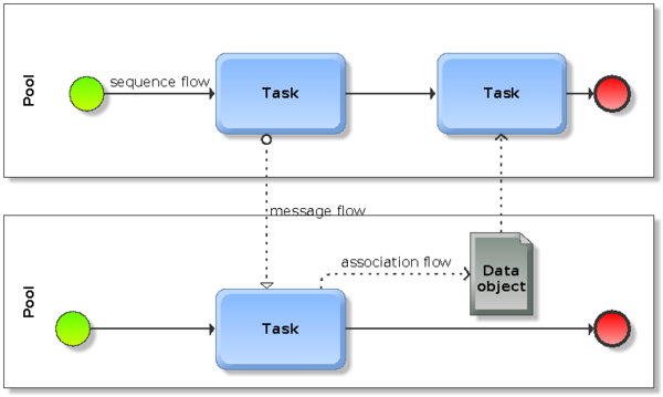
- Sequence flows define an order of activities performed in a process. Each flow has a single source (a start event, activity or gateway) and a single target (a end event, activity of gateway). Elements of a sequence flow are connected with solid arrows.
- Message flows either connect two pools or flow objects within these pools. As opposed to sequence flows, they cannot connect objects within the same pool. Message flows are represented with dashed arrows.
- Associations associate flow objects with information and artifacts and are drawn with dotted lines.
Message and sequence flows are usually drawn orthogonally, i.e. sequence goes in one direction (either top->down or left->right) and messages in the other as the following picture shows.
The BPMN 1.2 extended set
Most of the eleven core elements can by typed, e.g. an event can be either "none" (default), start, intermediate or end event. These sub-types then can be further "augmented", e.g. events may have an associated trigger. As an example, the start event may be a message start event (the process is triggered (starts) after receiving a message from an other participant)
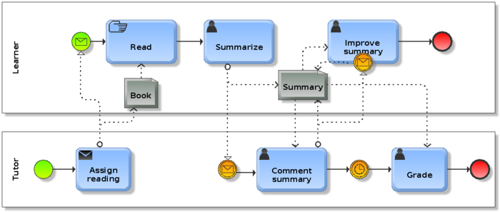
Below is a simple example of a pedagogical scenario. Tutor hands out a reading assignment, learner reads the book and then creates a summary with a online tool. The teacher will receive a message and then can provide some feedback. The student then has a revise it and the teacher will grade it after some deadline.
As you can see in the figure, tasks also can be typed. In this simple scenario, we use "manual tasks" (user reading a book), computer-supported "user tasks" (using the hand symbol) and a message task.
We will introduce some of these extended set further below.
BPMN process syntax and semantics
It is important to understand that there are many restrictions on how BPMN elements may be combined. The specification is easy enough to understand, but it is very difficult to get a global picture, i.e. what combinations of elements to use for a given process.
Overally speaking, the rules for connecting elements of a business process are fairly simple. Look at the previous figure for an example of a simple process that includes two participants (i.e. two sequence flows) and a message flow between these participants.
- Sequence flow rules
- Any flow object of start event, intermediate event, task, sub-process, gateway can connect to intermediate event, task, sub-process, gateway and end event. Or the other way round: no object can connect to start event, and end events cannot connect other events.
- Objects within subprocesses cannot connect to objects outside this process.
- Sequence flows cannot cross a pool boundary, use messages or signals for this purpose
- Message flow rules
- pools, subprocesses, tasks, intermediate message events and end message events can connect to pools, subprocesses, tasks, start message events and intermediate message events. Within this list, only start and event events behave differently: Start message events can only receive a message, but not send a message. End message events can only send messages but not receive messages. Let's recall that start events start a process and end events end a process.
There are no limitations with respect to drawing, exit and entry points of connecting lines can be anywhere on the border of an object. However, it is obvious that a flow diagram should be as simple as possible (mostly straight lines and little overlaps).
BPMN 1.2 event elements

Events
An event is something that "happens" during a process and it will affect the flow of the process. It usually has either a cause or an impact or both. In more operational terms, events will affect the sequence of the timing of process activities.
There are three main types of events: start events, intermediate events and end events. Events are represented as small circles.
Start Events
Start events indicate the initiation of a process and are usually associated with a trigger. The five types of triggers defined by v. 1.1 are represented with graphical markers.
- Plain (generic) start events
- do not specify any trigger
- Message start events
- start when a message is received from an other participant
- Timer start event
- indicate a given time/date for starting
- Conditional start events
- a process is triggered when certain business conditions become true.
- Signal start events
- A signal arrives that has been broadcasted from another process
- Multiple start events
- Defines multiple ways of triggering a process.
Intermediate events
There are 10 types of intermediate events in BPMN 1.2. All of these can respond to (catch) a trigger and some can set off (throw) a trigger. Catching events (only) also can be directly attached to the boundary of an activity.
Events are drawn as double circle. Catching event markers are drawn with strokes and throwing events are drawn filled.
- Simple ("none") intermedia event
- Events in the main flow of the process that are not further specified.
- Message (catching and throwing) intermediate events
- When catching, a message arrives from a participant and triggers the Event. If the process was waiting for the message it then can continue. Messages also can be used for exception handling, i.e. the process will continue differently.
- When throwing in normal flow, a message is sent to another participant.
- Summarized, messages are used to receive/send between 2 participants A and B.
- Timer (catching) intermediate event
- A set time/date will trigger the event, i.e. also inserts a delay
- Error (catching) intermediate event
- Only can be used in the boundary of an object. Can either catch a named error or all errors if none is specified
- Cancel (catching) intermediate event
- This cancel event must be used in the boundary of a transaction subprocess. It can be triggered either by a message or by a cancel end event in the subprocess.
- Compensation (catching and throwing) intermediate events
- When catching, a compensation activity attached to this event will be triggered.
- In normal flow, when throwing an event is defined, this event will be triggered, else "compensation" is broadcasted to all activities in the process.
- Conditional (catching) intermediate event
- Event is triggered when a condition becomes true
- Link (catching and throwing) intermediate event
- Links connect two sections of a process (at the same level), e.g. to implement looping, goto or simply move to a "next page". There can be multiple source, but only one target link.
- Signal (catching and throwing) intermediate event
- Signals can be sent and received accross process levels, pools and even diagrams. As opposed to messages, targets cannot be identified, i.e. there is always a specific source (throwing) but specific target. In other words, a signal is like a flare. Catching events must be attached to the boundary of an activity.
- Multiple (catching and throwing) intermediate event
- In normal flow, a multiple event can either catch or throw various events. When attached to an activity it can only catch.
End events
- Simple ("none") end event
- showing that and where a process ends
- Message end event
- indicates that a message is sent to a participant when the end of the process is reached
- Error end event
- an error code should be generated. This code then can be caught by an error catching intermediate event in the parent. If there is none, then the system also can handle this.
- Cancel end event
- is only used in transaction sub-processes and will signal that this transaction should be cancelled.
- Compensation end event
- can either compensate an activity that is identified. Otherwise all activities in the process can be subject to compensation if they have a compensation intermediate event attached.
- Signal end event
- a signal is generated. It will be broadcasted to any process (i.e. signal catching events) that can receive it. A signal is different from a message. The latter always has a source and a target.
- Terminate end event
- triggers an immediate end to the process and all its activities. The process is ended without compensation of event handling.
- Multiple end event
- multiple consequences of ending the Process.
Activities
(to do)
An activity stand for the work that company performs. An activity can be atomic or non-atomic (compound). The types of activities that are a part of a Process Model are:
- Tasks
- Sub-Process
- Process, but these are represented with swimmlanes
Simple tasks
An "atomic" (simple) task is a simple activity performed within an organization. The correspond to a step in the process flow. Tasks and Sub-Processes are represented with rounded rectangles.
Gateways
(to do)
Some design patters for connecting objects
(to do)
Examples
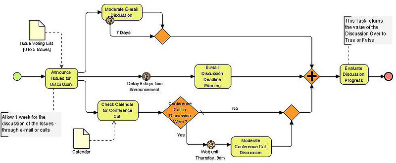
Model of a discussion
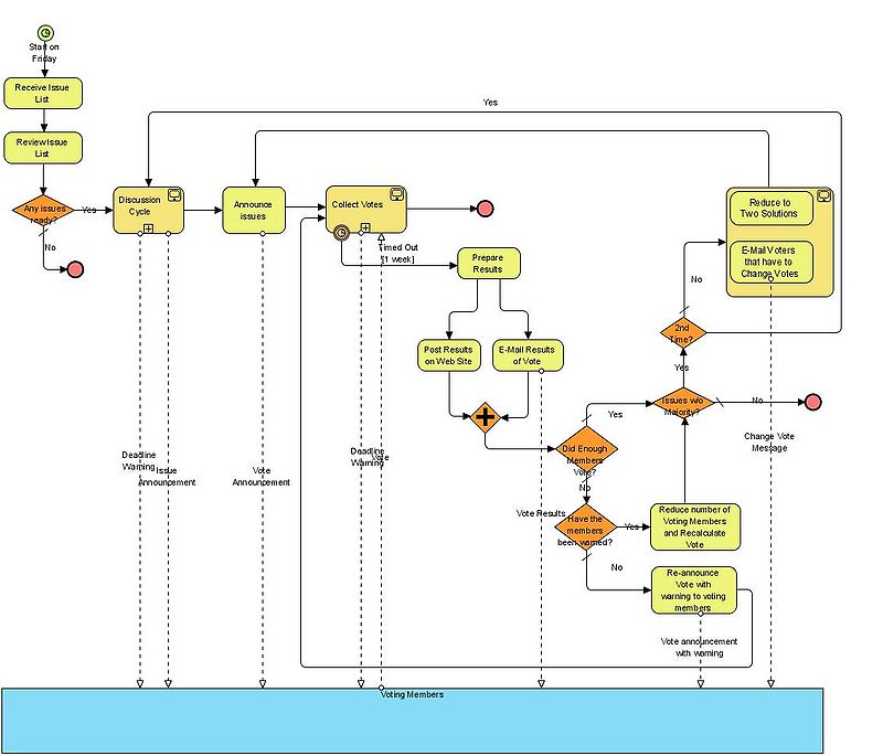
Email voting process
Model of surgery programming
The process model presented by Roja et al. (2008) shows at a high level abstraction the programmed surgical patient (PSP) process and the activities that are carried out when a patient is admitted into the hospital for the accomplishment of the surgical treatment of a disease that has been clinically diagnosed previously. This model is a result of a joint work between hospital and BPMN expert and it has been obtained through a reiterative and incremental method.
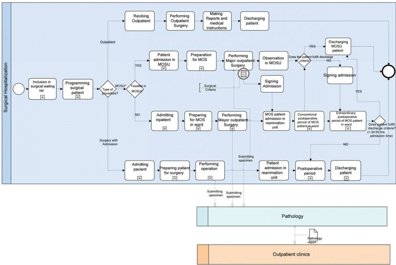
“The modelling of the programmed surgical patient process and its subprocesses has allowed to us to prepare an understandable model for the involved health professionals and make the communication of processes easier. Additionally, modelling allows early detection and correction of errors. This work is an essential previous step for further analysis and improvements in healthcare processes, including the adoption of information technology standards.” (Roja et al. (2008))
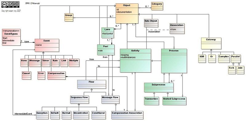
A BPMN 1 meta model
A more difficult to understand meta-model (i.e. an inofficial UML class diagram of BPMN was published by WSPER ("whisper").
Links and bibliography
See BPMN for more links and references
- Dive into BPMN
- Modeling Workflow Patterns through a Control-flow perspective using BPMN and the BPM Modeler BizAgi by Marcus Goetz, Institute of Applied Informatics and Formal Description Methods University Karlsruhe (TH).
- BPMN_Tutorial.pdf by Martin Owen and Jog Raj, Popkin Software


