Stitch Era - creating embroidery patches: Difference between revisions
| Line 102: | Line 102: | ||
* Check if the lines are in position (I had to fix one mistake, i.e. a drag a control point) | * Check if the lines are in position (I had to fix one mistake, i.e. a drag a control point) | ||
* Adapt the colors, e.g. Use black for the cut line. | * Adapt the colors, e.g. Use black for the cut line. | ||
* Finally, digitize the two lines, i.e. select the two, Embroidery tab, Art-to-stitch (line only) | * Finally, digitize the two lines, i.e. select the two, Embroidery tab, Art-to-stitch (line only) | ||
Alternatively, one also could decide to use the <code>Applique</code> fill type for the background. It allows defining placement stitches (useful if you plan to cut out the textile and then glue it inside), and both a running tackdown and a zigzag tackdown. | |||
[[File:3d-printing-icon-12.png|thumb|none|600px|Using Applique fill for the background (not tested alternative strategy)]] | |||
Notice: Above, we used the "menu" display in the object inspector (one can change using the little "3 dots" pull-down menu). Functionality is the same. | |||
=== Final adjustment === | === Final adjustment === | ||
Revision as of 13:55, 13 December 2017
Introduction
This article describes how to create embroidery patches, also called cloth badges for example, and that you can attach to cloth by various means.
A typical embroidery patch has the following properties
- It is stitched on some solid fabric (or special plastic)
- It usually covers the whole surface
- It is relatively small, i.e. 3cm to 8cm
- It can have various shapes, e.g. astronaut patches are round.
The difficulty consists in getting the borders right.
Example study - 3D printing badge
This study will show how to transform an icon from the noun project into a badge (including dealing with some technical difficulties).
Digitizing an icon
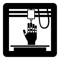
Let us start with a 3D printed hand from the noun-project.
Before importing it to Stitch Era we made some adjustment to the SVG in Inksacpe
- Adjust size to 8cm by 8cm using Inkscape.
- Adapt document size to drawing size plus 1mm (File -> Document Properties)
- Save as optimized SVG
- Save as simple SVG
Import to stitch Era, adjust size (again) and ungroup
- Importing to Stitch Era was OK, but the size was wrong
- Artwork Tab -> Layout. Set the size to 80
- Artwork Tab -> Layout. Un group all
We now have three vector objects, i.e. the printer, the hand and a platform. We changed colors for each one.
Since a back is supposed to be stitched fully, we now will add a background. The simplest way to do this, is to create a contour and then fill it:
- Select all or just the printer object
- Artwork Tab -> Layout. Click on
Contour with Offset - Select Custom and keep the defaults (outer offset)
- Kill the superfluous objects created inside the printer (2 red vector lines)
Now transform the red rounded rectangle into a light blue filled rectangle with a fat border.
- Move this new object on top: Either drag it to the top in the object manager, or use the Artwork -> Layout Tab -> Forward & Backward menu
You now can digitize using "Art to Stitch" as explained in several beginners tutorials, e.g. Stitch Era - creating embroidery from vector images
- Select All
- Select Embroidery Tab
- Art-to-Stitch (intelligent) using default values
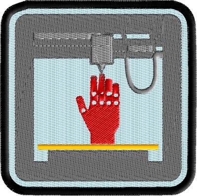
The simulated result looks like this, i.e. the 3D printer is not correctly rendered and the red hand would need some adjustment at the stitch level. The result is usable, but we would like to have something that is slightly better.
Dealing with SVG paths that Stitch Era cannot handle properly
Unfortunately Stitch Era cannot deal with SVG path that have holes inside, i.e. the printer will appear differently than planned.
- We tried "Trim shapes" and "Simplify to not effect".
We now have two choices
- either accept the result (i.e. a more massive 3D printer with most holes filled)
- or else either exporting the printer shape, and reimporting it as PNG image or start from the original SVG (export the printer shape from Inkscape) and then vectorize the raster image.
We just exported the "printer" shape as *.emf, transformed it with the "paint" program (any program can do) to PNG. We then imported the PNG image and then vectorized it as explained in the Stitch Era - creating embroidery from raster images. This took no more than 2 minutes.
We also decided to remove the holes from the hand (Artwork -> Layout -> Remove holes) and to smooth it.
- Select the printer and the hand and use Artwork -> Layout -> Combine Vectors -> Trim Shapes (do it 2-3 times)
The final vector shapes are below:
Now the question is whether we want to work with two layers, i.e. fully stitch the blue background and the rest on top or whether we just want to fill in the empty spaces with the background. Since patches are supposed to be rather stiff we can go for a a two layer version.
Since we only have four objects and since we want to digitize these objects in different ways, we will do one by one.
- Select the background
- Select Embroidery tab
- Art to Stich (Area only), Select
Fill areas and Borderlinessince we do need a fat separate zig-zag stitch for the border.
Next, use the same procedure for the other three objects, but
- Art to Stitch (Areay only), select
Fill areas
The result looks like this:
Adding a tack down and cut lines
Depending on how we plan to create the patch, we need a tack down line that will help attaching the cloth to the stablizer and a cut line that does the same but will also be used for cutting (see later).
To do this we will again use the "contour" function:
- Untick the green "Embroidery" button and tick "Auxiliar" if not visible.
- Click on the blue background vector
- Add two contour lines (a) one that is 0.5mm off the black border and (b) one that is a bit more inside. To do so, use "Custom", "Inner offset" and set the offset to 0.5mm and the other to 3.5mm.
- Check if the lines are in position (I had to fix one mistake, i.e. a drag a control point)
- Adapt the colors, e.g. Use black for the cut line.
- Finally, digitize the two lines, i.e. select the two, Embroidery tab, Art-to-stitch (line only)
Alternatively, one also could decide to use the Applique fill type for the background. It allows defining placement stitches (useful if you plan to cut out the textile and then glue it inside), and both a running tackdown and a zigzag tackdown.
Notice: Above, we used the "menu" display in the object inspector (one can change using the little "3 dots" pull-down menu). Functionality is the same.
Final adjustment
Reorder the stitch objects
- The tackdown and cut lines must come first
Move the border object to the end
- In the object manager drag it down.
Densify the black border (6 stitches/mm)
- Select the border objects and in the object manager (or on top) change density to 6
Add machine stop commands
- one after the cut line (object #2)
- (optional) one after the last design object, i.e. before the border is being stitched, e.g. the red hand

